Introduction to Class-A Class-A (or ‘Strak’) is a term used in specifically in automotive design. It describes the final production surface data for the aesthetic parts of the car. The term ‘Class A’ is often misunderstood, but it’s generally seen as the ‘Holy Grail’ of surface modelling. This is because as it achieves the highest […]
What Is a Class A Surface? G0 to G3 Continuity Explained
日本語版はこちら → · Deutsche Version →
Class A is not a compliment paid to a surface. It is a state the geometry is either in or not in. A surface qualifies when three things hold at once: continuity to the order the programme requires (G2 as the working baseline, G3 where a reflection would otherwise reveal the seam), a patch structure that follows the form, and clean behaviour under visual analysis. Everything below is how that is built, and how it is checked.
Class A, A-surface, Strak: one discipline, several names
Different studios and regions name this work differently — Class A, A-surface, A-class, technical surfacing, and in German-speaking programmes Strak. They mean the same thing: the surface set that carries the visible form of the product, built to curvature continuity and judged by how it behaves under light rather than by dimension alone.
The German word is the more honest one. Strak comes from shipbuilding — the fairing of a hull, pulling a line until it runs true. Not decoration. Fairing.
The practical consequence is worth stating plainly, because it is the reason the discipline exists at all: a surface can be dimensionally correct, pass every tolerance check, assemble perfectly — and still look cheap, because the curvature stutters somewhere a reflection crosses it. That failure is invisible in a CAD viewport. It appears under the lights of a showroom, or in the first press photograph.
The continuity ladder: G0, G1, G2, G3
Continuity describes how two adjacent surfaces meet. Each level contains the one below it.
- G0 — positional. The two surfaces touch. There is no gap and no overlap. Nothing else is promised: the form can change direction abruptly at the joint, and the eye reads a crease.
- G1 — tangent. The surfaces also share a direction at the joint. The crease disappears to the hand, but not to the eye: a reflection crossing the boundary changes width suddenly, because the curvature on either side is different.
- G2 — curvature. The surfaces share the same curvature value at the joint. A reflection now crosses without a visible break. This is the working baseline for visible automotive surfaces and for most premium product exteriors.
- G3 — rate of change of curvature. The curvature not only matches at the joint but changes at the same rate across it. On a large panel under a long light source, G2 can still show a faint flicker where a highlight crosses; G3 removes it.

The same boundary at four levels of continuity. This is the check, not a render.
The useful way to hold this: G1 satisfies the hand, G2 satisfies the eye, G3 satisfies the camera.
Why G2 is the baseline and G3 is not automatically better
G3 costs more than G2 — in patch count, in build time, and in how hard the surface is to change later. It buys a visible improvement in specific places: long shoulder runs, roof-to-bodyside transitions, large single-curvature panels, anywhere a continuous highlight travels a long distance across a boundary.
It buys very little on a tight fillet, a short transition, or a surface nobody photographs. Asking for G3 everywhere is a way of spending money without changing the product.
The right pattern is the one most OEM standards already describe: G2 throughout, G3 nominated on the transitions that earn it. At PSH Design we build to G2 as standard and to G3 where the client’s standard calls for it or where the form tells us it is needed — and we say which is which when we hand the data over.
How continuity is actually verified
No single check proves a surface is Class A. Continuity is established numerically and then confirmed visually, because the two can disagree — a boundary can pass a numerical tolerance and still show under a light tunnel.
Numerical checks confirm that the boundary meets the stated tolerance for gap, angle and curvature deviation. In Alias this is surface continuity evaluation at the boundary and a whole-model check that also catches duplicates, slivers and short edges. These run fast and they are not optional, but passing them is the floor, not the standard.
Visual analysis is where the surface is actually judged:
- Zebra stripes. Parallel bands reflected across the surface. At G0 the stripes break. At G1 they meet but kink. At G2 they cross smoothly. At G3 they cross and keep their rate of taper.
- Curvature combs and cross-sections. The comb should step, not jump, at the seam. A sudden spike at a boundary means the numbers passed and the surface did not.
- Diagnostic shading — highlight flow, iso-angle, light tunnel. These simulate how the finished panel will behave under directional light. A flat spot, a low patch or a crowded control-point region shows here before it shows in clay.
- Curvature shading across the whole model. Reveals whether the form is fair as a whole, rather than fair boundary by boundary.
A surface set that passes numerical checks but fails under a light tunnel is not finished. In our experience that combination — clean numbers, poor highlights — is the single most common condition of data that arrives from a supplier described as “Class A”.
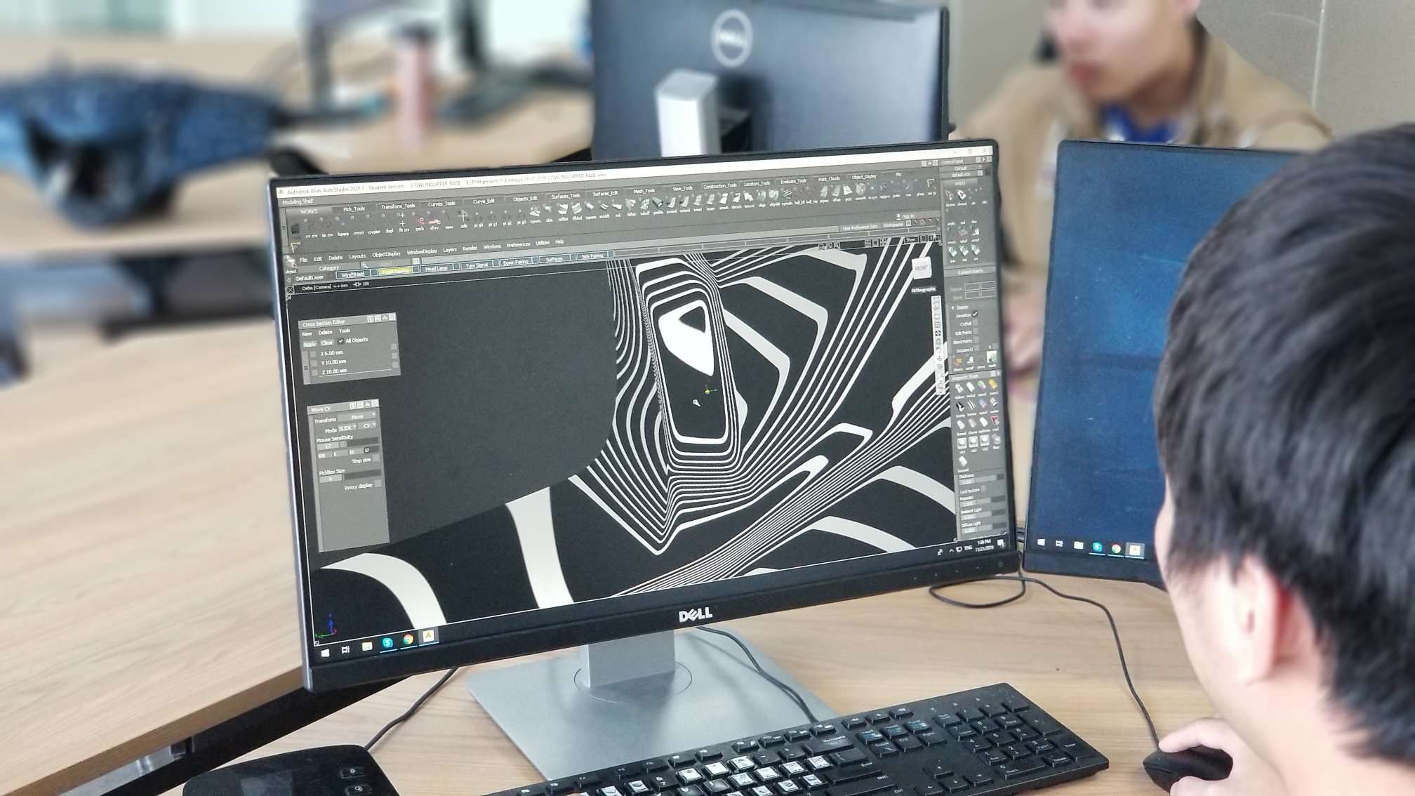
Continuity being checked the way it is actually checked — Cross Section Editor open over a zebra-shaded surface. PSH Design studio, Hanoi.
Patch layout is the part that cannot be automated
Before any analysis tool is opened, the structure of the data already tells you whether the surface can hold a highlight.
Three rules carry most of the weight:
- Boundaries follow the form. Patch edges run along the shape — with a character line, around a feature — not across it. A boundary cutting through the middle of a highlight run is a defect waiting to appear.
- Density rises only where curvature changes. Extra patches added to force a shape into place are a repair, not a build. They will show.
- Control points flow. The hulls should move across the form in an orderly grid. Crowded, twisted or unevenly spaced control points produce surfaces that look acceptable shaded and fail under zebra.
This is the reason Class A surfacing is learned on the job rather than from a course, and why the same brief given to two modellers produces data of visibly different quality. The tools are identical. The layout decisions are not.

An in-house PSH Design canopy with the patch boundaries drawn over the zebra. The boundaries follow the form; none of them cut across a highlight run.
Tolerances: why there is no universal number
There is no single tolerance that defines Class A, and any supplier who quotes one without asking about your programme is guessing.
What an OEM surface standard actually specifies is a set of figures that vary by context:
- By surface class — A-surfaces (seen and touched), B-surfaces (visible but secondary), C-surfaces (structural, hidden). Tolerances tighten as visibility rises.
- By location — exterior panels, interior surfaces with grain, interior surfaces without grain.
- By feature type — main blends, secondary fillets, detail fillets and shut-line edges each carry their own figures.
These standards are proprietary to each manufacturer and are part of what a surfacing team learns inside the industry rather than from published sources. Practically, this means one thing for anyone commissioning the work: send your standard with the brief. We build to your figures and report against them. Where no standard exists — which is normal outside automotive — we propose a set, state it in writing, and hold the data to it.
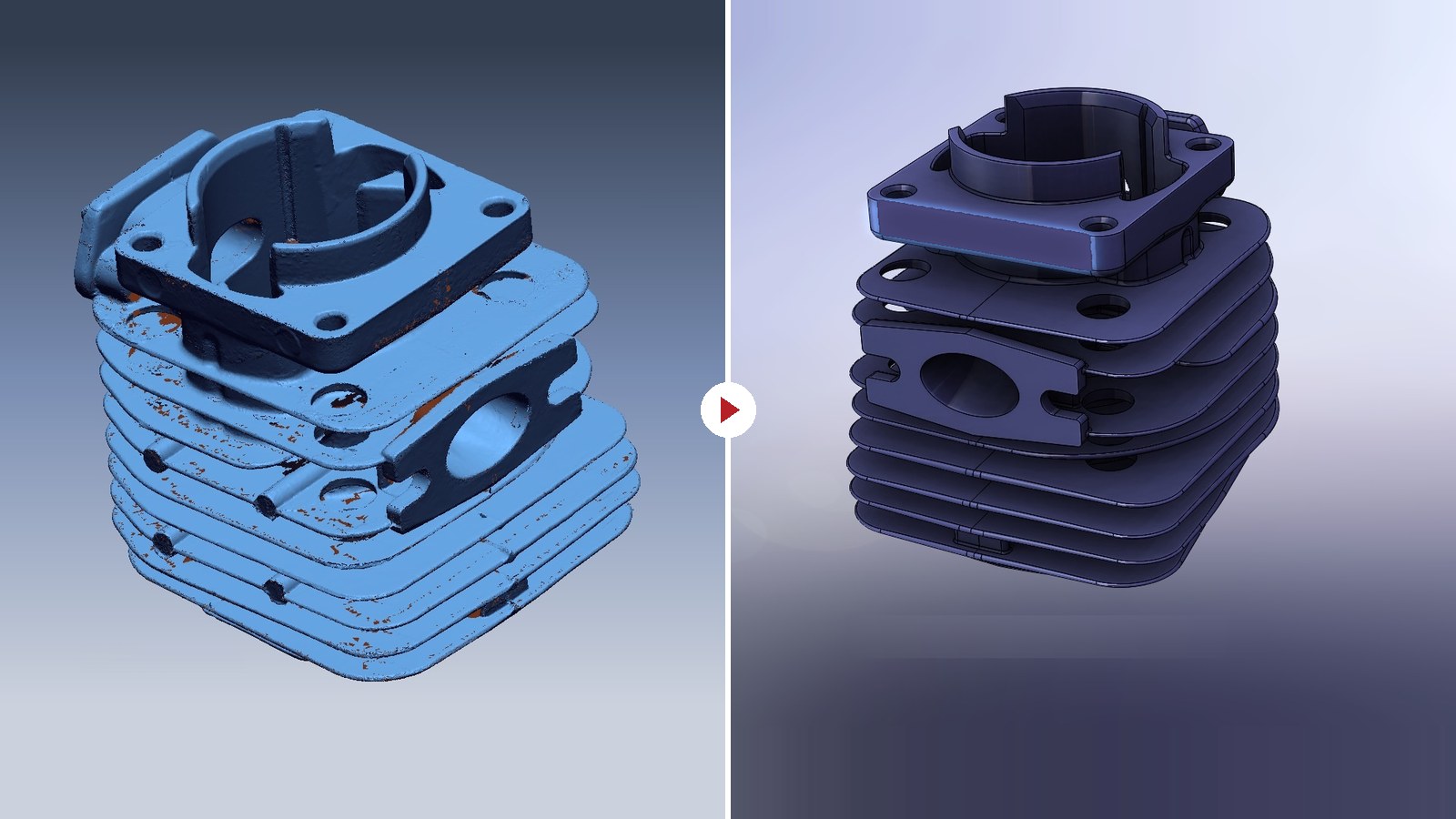
Class A from scan data
Not every Class A job starts from a styling model. A large share starts from something physical: a clay, a milled prototype, a competitor part, a tool that exists but whose data does not.
The scan is not the answer. Scan data always carries noise, and the physical object carries its own imperfections — a hand-finished clay is not a mathematical form. Rebuilding it faithfully would reproduce every one of those flaws in production geometry.
The skill is separating the intended form from the accident. A surfacing engineer working from scan data has to hold the design character exactly — the section a designer fought for, the run of a shoulder — while rejecting the ripple that came from a thumb, a scanner artefact or a warm afternoon in the studio. Meeting the scan to tolerance is the easy half. Knowing which deviations to honour and which to discard is the work.
This is where our reverse engineering and Class A disciplines meet, and it is why we keep them in the same building rather than in two companies.
When Class A is applied — and when it is too early
Class A modelling is slow and methodical by design. It belongs on a locked form.
During concept work the shape is still moving, sometimes daily. Imposing full Class A discipline there wastes the effort, because the surfaces will be rebuilt. What helps enormously is the opposite: building concept data with Class A logic in mind — sensible section structure, clean topology, boundaries that already follow the form. Concept data built that way hands over to a Class A team in days. Concept data built without it hands over in weeks, or gets rebuilt from scratch.
That handover is the most commonly underestimated cost in a programme. It is also the easiest to remove.
How to check Class A data you have been sent
This section is for the person receiving surface data rather than building it — a design director, a technical lead, an engineering manager deciding whether to accept a delivery.
You do not need to be a surfacing specialist. You need to insist that five things exist, and look at them:
- A zebra or reflection image across the boundaries that matter — not a beauty render. Ask for the stripes crossing the shoulder, the roof rail, the door shut. Kinks are visible to anyone.
- Curvature comb plots at the seams, showing steps rather than jumps.
- A continuity report stating which boundaries are G2, which are G3, and against what tolerance figures.
- A view of the patch layout itself — wireframe or patch-shaded. Boundaries cutting across highlight runs, or dense clusters of small patches in a smooth area, tell you more than any report.
- A model check confirming no duplicate surfaces, no sliver patches, no unintended gaps.
If a supplier cannot produce these, that itself is the finding. Data that has genuinely been built to Class A standard generates this evidence as a by-product of the work; producing it afterwards for a surface set that was not built that way is difficult, which is exactly why the request is useful.
Questions engineers ask
What is a Class A surface?
A surface built to curvature continuity — G2 as the baseline, G3 where required — on a patch structure that follows the form, and validated by visual analysis such as zebra stripes and curvature combs rather than by dimensional tolerance alone. It is the surface set that carries the visible shape of the product.
Is Class A the same as Strak, A-surface or A-class?
Yes. They are regional and studio names for one discipline.
What is the difference between G2 and G3 continuity?
G2 means adjacent surfaces share the same curvature at the joint, so a reflection crosses without a break. G3 means the rate of change of curvature also matches, which removes the faint highlight flicker that can remain on large panels. G2 is the usual baseline; G3 is nominated where it earns its cost.
Can ordinary CAD software produce Class A surfaces?
It can produce surfaces that meet the numbers. What general CAD lacks is the evaluation and direct control-point editing the discipline depends on — which is why this work runs in Alias and ICEM Surf, the two toolsets built for it.
How do I know whether the data I received is really Class A?
Ask for zebra images across the boundaries, curvature combs at the seams, a continuity report naming the tolerances, a view of the patch layout and a model check. See the section above.
Can existing CAD be brought up to Class A quality?
Often, yes — but it is usually a rebuild of the visible surfaces rather than a repair. We look at the data first and tell you which of the two it is before quoting.
Does Class A apply outside automotive?
Yes. Any product whose value depends on how a surface reads under light — premium appliances, consumer electronics, aircraft and rail interiors, marine — uses the same discipline, usually without an in-house standard to work to.
Where this fits
This article defines the standard. Two neighbours cover the rest: Class A surfacing sets out how we run the work and what a delivery contains, and CAS design and Class A modeling follows the path from concept to production surface.
PSH Design has built Class A surfaces for 17+ years, in Alias and ICEM Surf, to OEM acceptance standards — from styling data, from scan data, and from other people’s CAD.
Send one part and see the data: https://pshdesign.com/rfq-free-test-project/
—-
📚 FURTHER READING
1. Continuity G0, G1, G2, G3
Autodesk — Alias Help. The reference definition of geometric continuity, including construction tolerances and the evaluation tools named above.
Link: help.autodesk.com — Continuity G0 G1 G2 G3
2. CATIA ICEM Surf — Advanced Surface Modelling
Dassault Systèmes. The explicit surface modeller used as the OEM reference for Class A work.
Link: 3ds.com — CATIA ICEM Surf
3. Metrology of Class A Surfaces in Automotive Manufacturing
Industrial Inspection & Analysis (IIA). How Class A surfaces are measured and verified once they are physical.
Link: industrial-ia.com — Metrology of Class A Surfaces
PSH Design
17+ years of CAS, Class A Surfacing, CAD and Reverse Engineering for Automotive, Aerospace, Medical and Industrial, to OEM standard.
Concept Design & CAS · Class A Surfacing · CAD Engineering · Reverse Engineering
Work of this kind is easier to judge than to describe.