CAD Engineering
CAD Engineering
CAD engineering is a wide field. We have chosen not to cover it. What we do instead is go narrow and go deep — into the work where CAD skill alone is not enough and the answer depends on thinking like a mechanical engineer.
First part at our cost · Pay only when you are satisfied · NET 30 · Every model warranted for life
Since 2009
Cubing and body engineering
Complete modules
Class A to production CAD, one team
17+ years
Surfacing to OEM design-centre standards
Narrow By Choice
Most CAD suppliers widen. They add industries, add software, add headcount, and end up able to attempt anything and answerable for nothing. We went the other way, and we accept what that costs us.
There is a kind of work where the CAD is the easy part. Reading a vehicle you did not design. Deciding where a full-size master should be split. Knowing which surface a customer will actually judge you on. None of that comes out of a modelling course — it comes from mechanical engineering, and it is the reason our people are engineers first and CAD users second.
What we do not take on:
- General mechanical CAD outside automotive body and interior work
- Machine and plant design
- Electrical, harness and control systems
- Screen and software interface design
- Model correction or feasibility work on models built elsewhere
Saying this plainly saves both sides a month.
Cubing and E-Cube Design
A cubing model — in German, the Meisterbock — is a full-size master of a vehicle body, machined from solid aluminium and assembled to reproduce the car as one rigid, dimensionally stable reference. An E-Cube covers the structural zones and mounting points rather than the whole body. Both exist so that panel gaps, seam alignment and the real fit of trim, lighting and interior parts can be proven before tooling locks in.
We design them. We do not machine them — and that is deliberate. Design is where our engineering depth sits, and it is what we intend to do better than anyone.
A whole-car cube runs to roughly 1,000 hours of design work. That figure is worth knowing before you enquire: it tells you the scale of engagement this is, and it is the number we have arrived at doing this since 2009.

A whole-car cube as a 3D assembly on its frame — the complete master, before it is broken down into machinable blocks.
A cubing or E-Cube design package from us contains:
- Body interpretation and scope definition — which surfaces and features the cube reproduces, and which it deliberately does not
- Segmentation and split strategy for machinability, stability, handling and measurement access
- Datum strategy and reference scheme tied to the vehicle coordinate system and the programme’s own reference points
- Locator and interface design between blocks, and for mating parts, trim, glazing and add-on components
- Modular structure design where local cubes or removable sections are needed
- Manufacturing-ready detailing — stock allowances, clamping and fixture provisions, lifting and handling features
- Native data in the high-end automotive CAD systems, plus STEP and IGES for handoff
If you want the discipline explained rather than the service described, we set it out at length in Cubing, Meisterbock and E-Cube Design for Automotive Bodies.
Four Steps From Body Data to Machined Blocks
The input is body-in-white CAD: hundreds of thin-walled stamped panels full of cavities, flanges and joints whose connection logic is not stated anywhere in the data. The output is a set of solid aluminium blocks that reproduce the same body as one rigid master. Getting from one to the other is the whole discipline, and it is not a file conversion.

The four steps every cubing package goes through, shown on our own cubing data.
The body-in-white assembly as supplied — every stamped part, every sub-assembly, in whatever state the programme is in that week.
Only the surfaces and features the cube has to reproduce. Deciding what to leave out is a judgement, not a filter.
Front floor, rear floor, bodyside, roof. The car is broken along lines that follow how it is built and how it will be measured.
Each package becomes machinable blocks. Bushings and fixing holes are designed in so every block locates positively against its neighbours.
Two decisions inside that sequence carry the whole job. Where the splits fall sets machining cost, handling, measurement access and, above all, how error accumulates along the length of the vehicle. And whose datum scheme governs — datum philosophies differ from one carmaker to the next, and the shop that will cut and assemble the blocks usually has conventions of its own. Establishing that before any modelling starts, and then adopting it exactly rather than imposing a house standard, is part of the work.
Where the Cube Meets Measurement
A cube is only a reference once it has been measured and shown to agree with the data it came from. That step is where cubing design is judged, and it reaches back into every decision made on screen months earlier.
Random scatter across the blocks points at machining. A deviation that grows steadily from the front of the vehicle to the rear points at the locating scheme. Which is why a cubing package has to be dimensionally unambiguous: every datum, every reference pad and every control zone in the model is something a metrologist will later have to find on the physical part and probe.
We read measurement reports as easily as we read drawings, because the same team has been rebuilding CAD from scan and CMM data for measurement bureaux since 2009. That work is described on our reverse engineering page.

Floor and bodyside packages assembled. This is where a weak locating scheme shows up as drift along the vehicle rather than as random scatter.
BIW Fixtures and Checking Fixtures
The same discipline, at single-part scale. A checking fixture holds one component in its vehicle position so it can be inspected against nominal; a BIW fixture holds parts in place while they are joined. Both live or die on the same two things a cube does — the datum scheme, and whether the part can actually be loaded, clamped and probed by a person in a hurry.
We design to European, US and Japanese drawing conventions, because the shop that builds the fixture and the quality department that signs it off are rarely in the same country as the programme.

One segment from a floor package. Every split line, locating feature and fixing hole on it was decided before a single cut was made.
Complete Automotive Modules
Your part sits in the carmaker’s vehicle and is judged against the carmaker’s own surfaces. That is the standard our surfacing people have worked to for 17+ years.
There is a structural difficulty in supplying a module to an OEM, and it is nobody’s fault. The standard your part is measured against is set by a studio you do not control, staffed at a depth built up over decades. Your own team was assembled to do a different job — and to do it well — but Class-A surface work is not usually where that depth sits.
A carmaker outsources surfacing when it runs short of capacity. A Tier 1 outsources it when the standard is set higher than the bench. Those are different problems, and the second one is where we are worth having.
What we can take on as a complete package:
- Cockpit and interior modules — instrument panel, console, door trim, as a coordinated assembly rather than a set of parts
- The physical side of the human interface — control layout, reach and ergonomic packaging, switchgear form, display surrounds and the surfaces a hand actually touches
- Exterior modules and add-on assemblies
- Class-A surfaces, Class-B engineering surfaces, and the production CAD underneath them, from one team
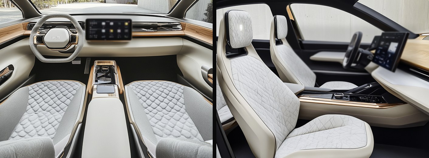
Interior concept studies from our own design tooling. The point of both images is the same one: the instrument panel, console, door and seat surfaces resolved against each other rather than signed off separately. Concept work — not a delivered programme.
We are open about where we stand: our depth is in surfaces and in body engineering, built over 17+ years of Class-A surfacing to the standards of top design centres in Germany, the UK and Japan. Complete module work is where we are directing that capability next. The sensible way to test it is one module, or one zone of one module, before anything larger is discussed.
Generative Design for Additive Structures
A bracket designed to be milled and a bracket designed to be printed are not the same object, and converting one into the other is not a matter of running an optimiser over the old shape — the load paths have to be understood, the printing direction decided, the material allowed for, and the result has to remain something a person can inspect and sign off. We are directing this at conventional structural assemblies that need to occupy less space and carry less weight while doing the same job.
The same approach already runs through our medical work: patient-specific cranial implants, where CT data is converted into CAD, the anatomy is reconstructed to clinical standards alongside the surgeon, and the result becomes a printable titanium design. One design, one patient, nothing repeated.
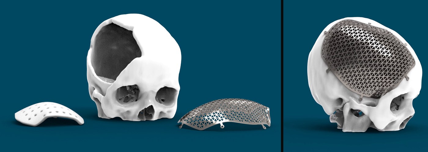
Our own work. Left: the reconstructed defect with two plate strategies — a solid plate, and a lattice built to the load path so the implant carries what it has to and no more. Right: the lattice version located on its fixing points. One design, one patient.
What Comes With Every Job
Native data in whichever of the high-end automotive CAD systems your programme runs on, so your team can carry on working. Plus STEP and IGES for anyone downstream who cannot open it. Both, not one or the other.
Technical drawings prepared to German, US or Japanese practice, with GD&T applied the way the receiving shop expects to read it.
Body data is never frozen when this work starts. The model structure is built to absorb releases without the assembly collapsing.
How Working With Us Runs
We design; we do not machine. Staying on one side of that line is why the design is as good as it is.
Manufacturing is coordinated through specialist cubing shops in Germany, Japan or China — placed wherever it sits closest to you.
You deliver to your customer under your name. We do not contact them, and nothing you send becomes portfolio material.
Every model is warranted for as long as you have it. If something turns out to be wrong — this month or in five years — we correct it at no charge.
Questions We Are Asked
Do you manufacture the cube as well as design it?
No. We design, and we coordinate manufacture through specialist cubing shops in Germany, Japan or China — whichever sits closest to you. Keeping the build near you matters more than where it is cheapest, because dimensional correlation and sign-off are moments worth attending in person.
How large is a cubing project?
A whole-car cube is around 1,000 hours of design work. Smaller scopes — an E-Cube, an exterior cube, a single package such as a floor or a bodyside — scale down from there. If your programme is smaller than that, say so early and we will tell you honestly whether it is worth our involvement.
Whose datum scheme do you work to?
Yours, or the programme’s, or the machine shop’s — whichever governs. Datum philosophies differ between carmakers and the shops that build the blocks often have their own conventions. Establishing which one applies before modelling starts is part of the job; imposing our own would not be.
Is cubing design the same as Class-A surfacing?
No. A cube is built from production sheet-metal data and is a dimensional engineering discipline. Class-A surfacing works on styling surfaces and is a surface-quality discipline. We do both, but they are different skills and we staff them differently.
You have not built a complete cockpit module before. Why should we start with you?
You should not start with a whole module. Start with one zone of one module, at our cost, and judge the surfaces against the standard you are actually held to. That is a fair test and it costs you a fortnight rather than a programme.
Can you work with our data if we cannot release the full vehicle?
Yes. A single zone with its interfaces is enough to work from and enough for you to judge us on. We sign your NDA, and back-to-back to your customer’s where your agreement requires it.
What do we get at the end?
Native data in the high-end automotive CAD systems, STEP and IGES, 2D drawings to your drawing convention with GD&T, and a model structure built to survive the releases that will arrive after we hand over.
CAD Engineering, in depth
 3D Reverse Engineering & AI Design: The Future Foundation of Medical Device...Read the article →
 Adding Reverse Engineering to an Inspection Business: What the Lab Keeps, What...Read the article →
 Navigating CAD Design Challenges in UK Automotive – Advanced Engineering 2025Read the article →
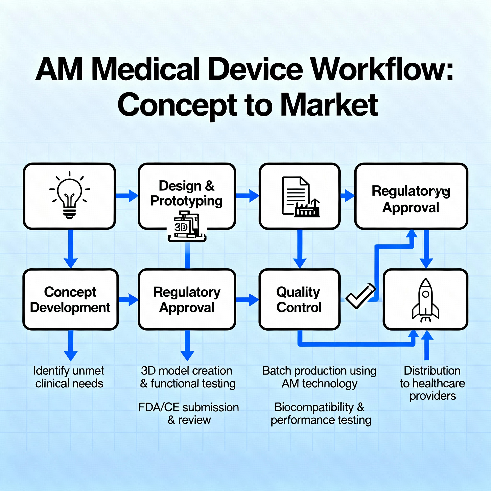 3D Printed Medical Implants & Instruments: Design to Clinical Trial Excellence in...Read the article →
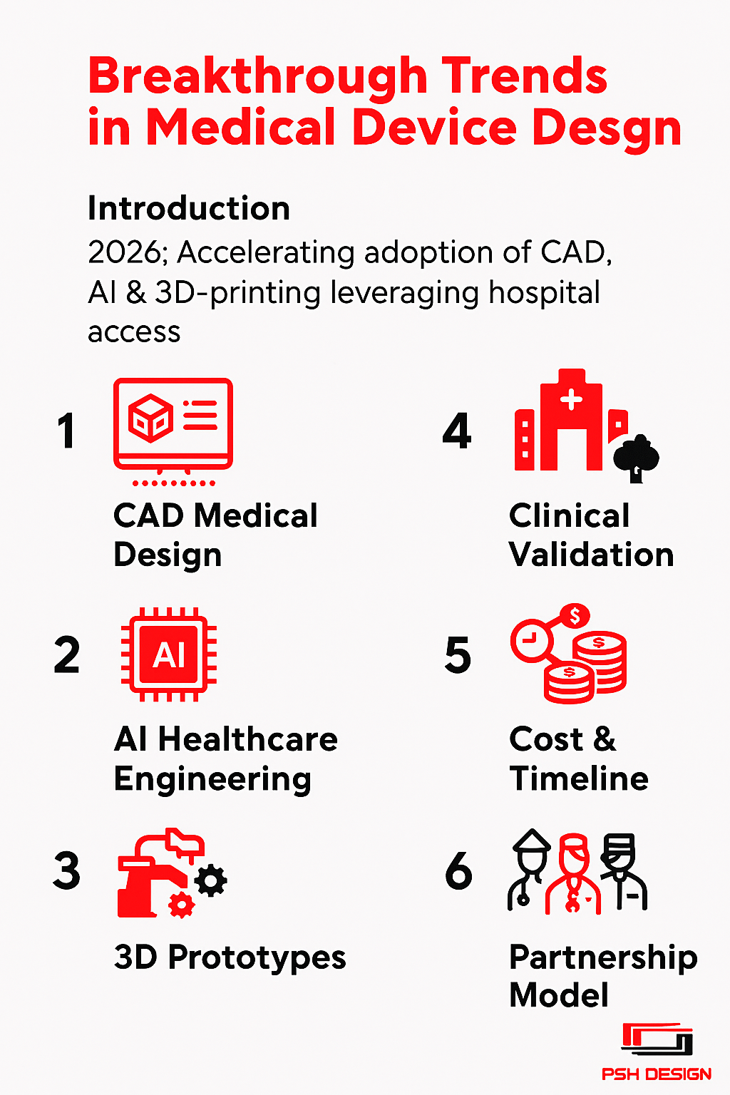 Breakthrough Trends in Medical Device Design 2025Read the article →
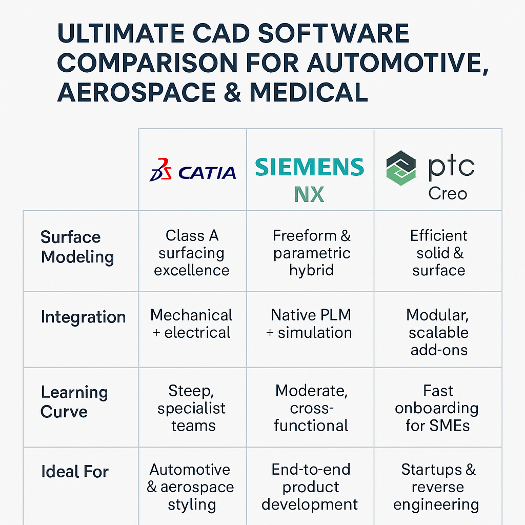 In-Depth Comparison: CATIA, NX, Creo for CAD Engineering 2025Read the article →
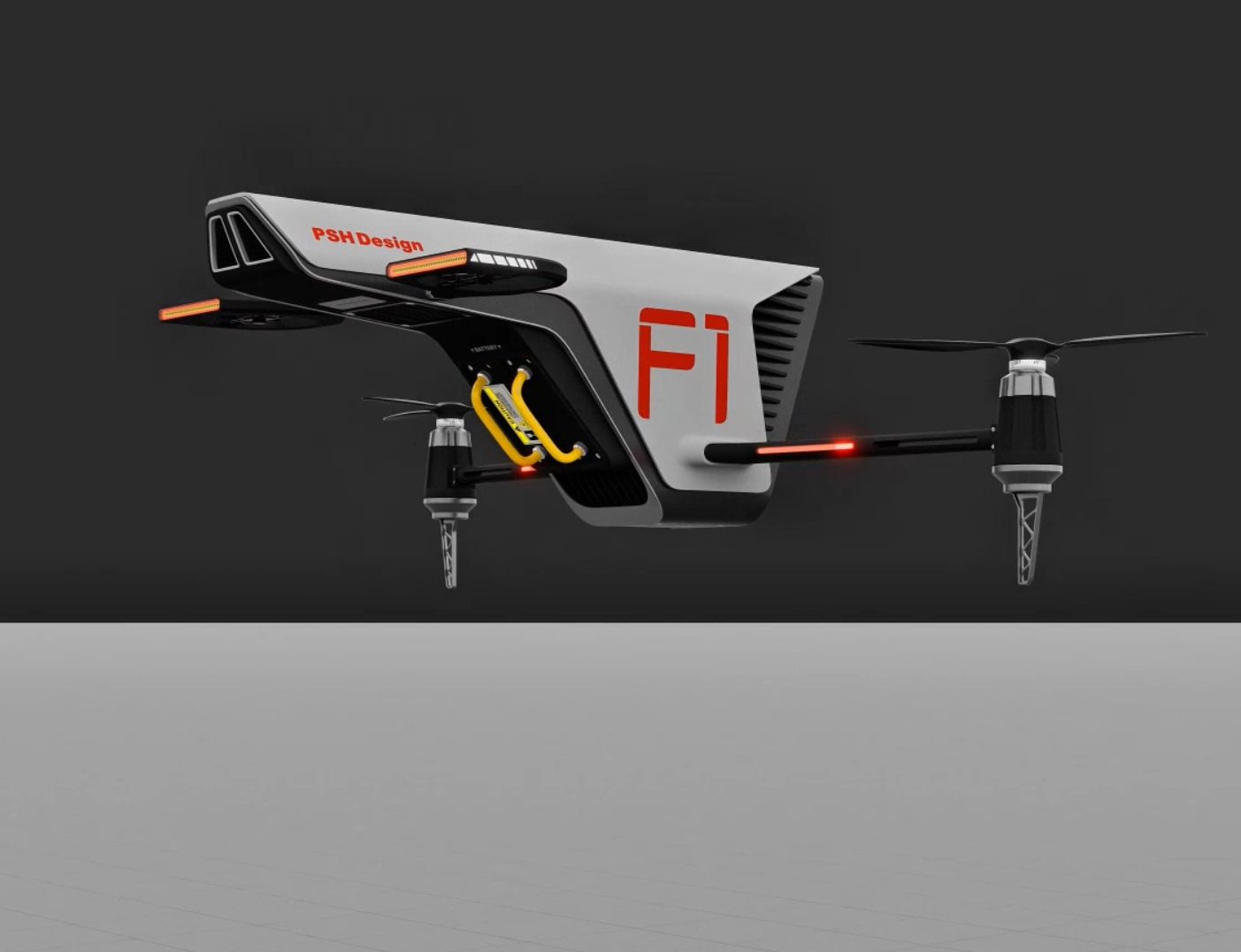 Mastering Drone Hardware Design : Top Challenges and How to Overcome Them...Read the article →
 From Concept to Market: How the Right CAD Software Accelerates Startup GrowthRead the article →
Start With One Zone
We cannot show you client names or programme files. The fastest way to find out what we can do is to let us do a piece of it. Send one body-in-white zone or one interface set and we will come back with a segmentation approach, a datum strategy, locator logic and our recommendation. The first one is at our cost.
If releasing data is awkward, a twenty-minute call will do. Describe the programme and the standard you are held to, and we will tell you plainly which parts of it we are good at and which we are not.