CAD File Formats: Which One to Send, and Which One to Ask For
日本語版はこちら → · Deutsche Version →
A CAD file stores a 3D model or a drawing. There are hundreds of formats, but almost all of them fall into three families. Native files belong to one CAD system and carry the model’s build history. Neutral files — STEP, Parasolid, IGES — open almost anywhere but keep only the geometry. Mesh files — STL, OBJ, PLY — are a skin of triangles, not a solid. Which one you need depends on what the person receiving it will do next.
Most articles on CAD file formats stop at a list. This one goes a step further: which format to send, and which format to ask for — seen from the side of a studio that rebuilds roughly 300 parts a year as CAD, from scan data, CMM data and drawings.
Three Families of CAD File, and What Each One Carries
File extensions run into the hundreds, but the question that matters is always the same: how much of the information about how the model was built is still in the file?
| Family | Examples | Carries | Loses | Use it when |
|---|---|---|---|---|
| Native | .sldprt · .prt · .CATPart · .ipt · .par | Geometry, feature tree, constraints, driving dimensions | Opens only in its own CAD system without translation | The recipient will keep editing the design |
| Neutral (B-rep) | STEP · Parasolid · IGES · ACIS · JT | Exact geometry, as a solid or as surfaces | Feature tree, constraints, design intent | Exchanging between different CAD systems, machining, archiving |
| Mesh | STL · OBJ · PLY · 3MF | Shape approximated by triangles | Exact surfaces, the solid, editable dimensions | 3D printing, visualisation, scan data |
| Point cloud | E57 · ASC / XYZ | Coordinates of every measured point | Everything except the points | Raw output from a 3D scanner |
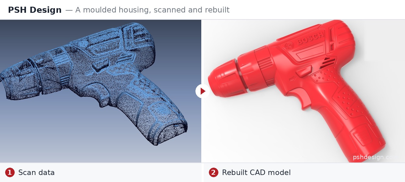
The easiest mistake to make: a mesh file and a CAD file of the same part look identical on screen. One is a photograph of the surface. The other is a model that can be edited, machined and inspected.
The Most Common CAD File Formats, One by One
| Format | Extension | Family | Owner / standard | Feature history? | Tolerances (PMI)? |
|---|---|---|---|---|---|
| SolidWorks | .sldprt .sldasm | Native | Dassault Systèmes | Yes | Yes |
| Creo | .prt .asm | Native | PTC | Yes | Yes |
| NX | .prt | Native | Siemens | Yes | Yes |
| CATIA V5 | .CATPart .CATProduct | Native | Dassault Systèmes | Yes | Yes |
| Inventor | .ipt .iam | Native | Autodesk | Yes | Yes |
| Solid Edge | .par .asm | Native | Siemens | Yes | Yes |
| AutoCAD | .dwg | Native | Autodesk | — | — |
| STEP | .stp .step | Neutral | ISO 10303 | No | Full semantic PMI: AP242 only |
| Parasolid | .x_t .x_b | Neutral | Siemens | No | No |
| IGES | .igs .iges | Neutral | US standard · v1.0 1980, last version 5.3 in 1996 | No | No |
| ACIS | .sat .sab | Neutral | Spatial (Dassault Systèmes) | No | No |
| JT | .jt | Neutral | Siemens · ISO 14306 | No | Yes |
| DXF | .dxf | Neutral (2D) | Autodesk | No | — |
| STL | .stl | Mesh | 3D Systems, 1987 | No | No |
| OBJ | .obj | Mesh | Wavefront | No | No |
| PLY | .ply | Mesh | Stanford University | No | No |
| 3MF | .3mf | Mesh | 3MF Consortium · ISO/IEC 25422:2025 | No | No |
| E57 | .e57 | Point cloud | ASTM E2807 | No | No |
STEP
The most widely used format for moving models between different CAD systems. STEP comes in several “application protocols”: AP203 and AP214 are the older ones you still meet; AP242 is the current one. It merges the two older protocols and adds full semantic PMI — tolerances and annotations a machine can read. If you can only pick one neutral format, pick STEP AP242.
Parasolid
Parasolid is both a file format and a kernel — the geometry engine inside a CAD system. SolidWorks (desktop), NX and Solid Edge are all built on Parasolid; CATIA V5 runs on Dassault’s CGM kernel, Creo on PTC’s Granite, and Inventor on Autodesk’s ShapeManager. That is why a Parasolid file moves between SolidWorks, NX and Solid Edge with far fewer problems than it does into a system with a different kernel. How much the kernel matters is a subject of its own — we cover it in what a CAD kernel is and why it matters.
IGES
A format from 1980 whose last version appeared in 1996, still requested largely out of habit. IGES typically describes separate trimmed surfaces rather than one closed solid, so it often opens with gaps between faces that have to be repaired. For almost every job, STEP has replaced it.
STL
The most common mesh format — and the format our customers send us most often. STL stores triangles and nothing else: no units, no colour in the standard version, and no solid. A file that measures 100 across could be 100 mm or 100 inches. Whoever receives it has to be told.
E57
A vendor-neutral format for 3D imaging data — point clouds plus images — standardised by ASTM as E2807. If your scanner can export E57, it is usually the cleanest way to send raw data.
What Gets Lost Between Formats
Every translation is a chance to lose information. What goes missing most often:
- The feature tree and constraints. Outside its own system, a model becomes “dead” geometry: you can push and pull faces, but there are no driving dimensions left. Why that decides whether a rebuilt model gets used at all is set out in You Bought the Scanner. Who Builds the CAD?
- Units. STL does not store them.
- Tolerances and annotations (PMI / GD&T). Only STEP AP242, JT and native files carry them in full.
- Colours, layers, feature names.
- A closed solid. CAD systems work to different geometric tolerances. When a model moves between two kernels, faces that met perfectly on one side can open into gaps and sliver faces on the other.
Which Format to Send Us: Reverse Engineering Input
We work with almost any format our customers send. But sending the right thing first time saves a round of questions.
| What you have | Send this | Also send, if you have it |
|---|---|---|
| 3D scan data | A mesh — STL, PLY or OBJ — or a point cloud: E57 or ASC | Photos of the physical part |
| CMM data | The inspection report plus the exported point file | The original drawing, if it still exists |
| Only a drawing | Photos, overall dimensions | |
| Old CAD that no longer matches the part | Both the old CAD and new scan data | Notes on what was changed on the part |
And four things we always ask before quoting:
- The units the file is in
- The coordinate system and datums — where the part mounts, which face is the reference
- Which faces are functional — mating faces, sealing faces, locating holes — and which are only an artefact of casting or machining
- Which CAD system the end customer uses — because that decides what we deliver
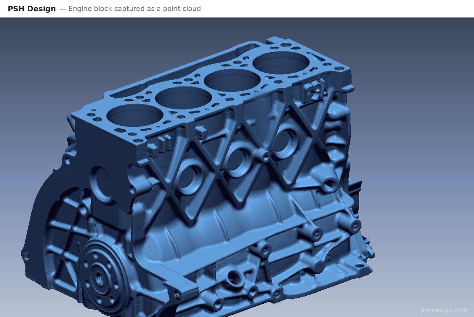
Scan Data Is Not the Only Way In: CMM Points Work Too
Many inspection labs were measuring parts on a CMM long before structured-light scanners became common, and they trust those points more than any mesh. They are right to: each CMM point is typically measured more accurately than a scan point, and it sits exactly where the measuring engineer decided the part matters.
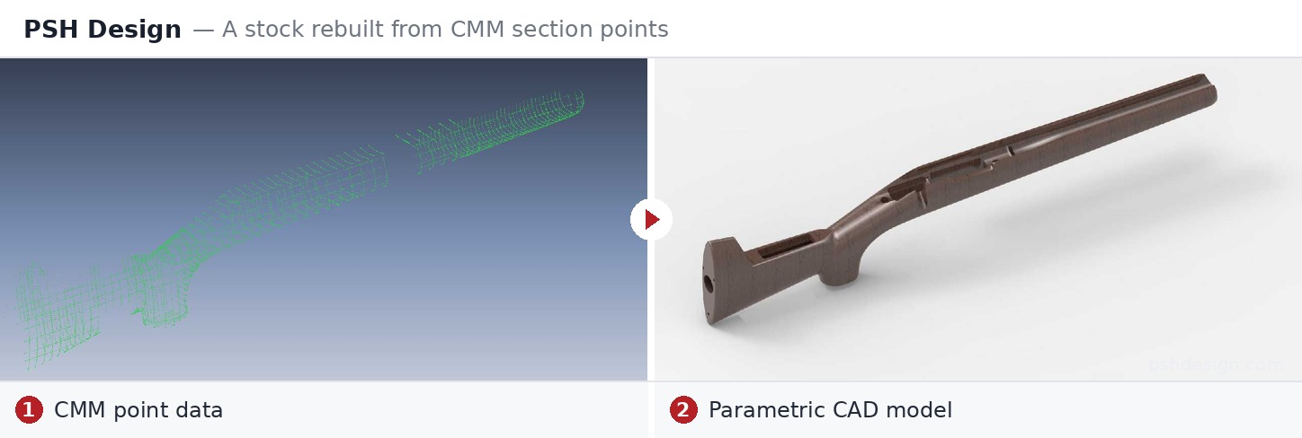
A CMM point file on its own is enough for us to build a full parametric model — no scan needed. Sections and profiles measured on the CMM become sketches, the sketches become features, and what you receive is a native model with a feature tree, like any other job. It is work we do regularly for metrology labs.
What to send: the exported points (a plain-text or CSV point file, or IGES points), the inspection report, and a sketch or photo showing where the sections were taken and which datums were used. If the sections miss a feature that matters, we tell you before quoting — while the part is still on your table.
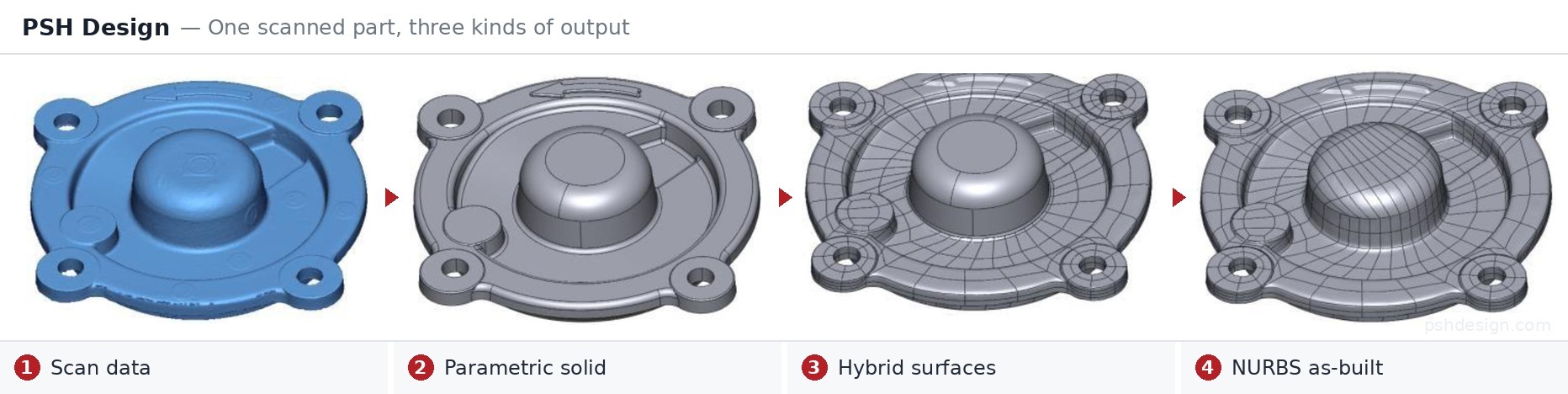
Which Format to Ask For: Exporting CAD Models from Scan Data
The right question is not “which format is best” but “what will the recipient do with this file next?”
| What happens next | Ask for | Why |
|---|---|---|
| The design will be modified | Native, in the CAD system of whoever modifies it | The feature tree and driving dimensions survive |
| CNC machining / CAM programming | Native, or Parasolid / STEP | CAM needs exact geometry; native is easier if small changes come up |
| Mould, tooling or fixture design | Native | Draft, shrinkage and parting lines will be added — it has to be editable |
| Comparing against a new scan | STEP plus a deviation report | Only reference geometry is needed |
| 3D printing | STL or 3MF | Printers read meshes |
| Long-term archive | STEP AP242 and native | STEP still opens in years to come; native stays editable |
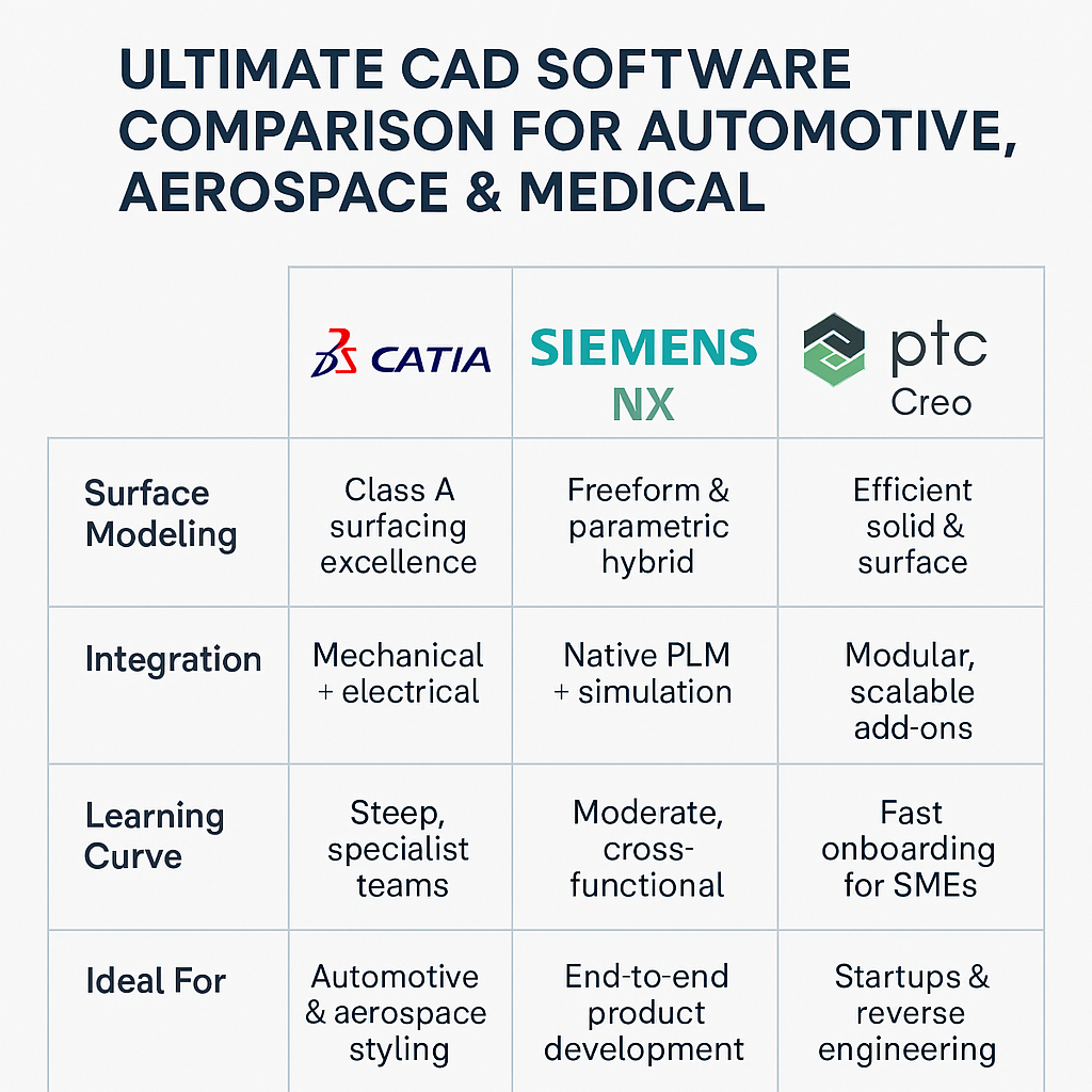
Our rule: deliver native, in the CAD system the end customer runs, with STEP alongside. We deliver native in eight systems: SolidWorks, Creo, CATIA, NX, Inventor, Solid Edge, AutoCAD and Revit. How the three biggest of them differ is covered in CATIA vs NX vs Creo.
Why Not Every Studio Can Deliver Native
This is the thing many customers do not know — and the most common mistake we see: they are not sure what a native file is, or they do not know they can receive one in their own CAD system. Many assume that anything rebuilt from scan data arrives as STEP.
It does not have to. But not every studio can do it.
To deliver a native file that looks as if it had been modelled in that system from the start, the person rebuilding it has to master two things: the reverse-engineering software, and the target CAD system itself — deeply enough to rebuild the model with that system’s own features, not just import a lump of geometry into it.
Put simply, the person rebuilding the part has to be able to recreate its shape at the level of the engineer who made the original CAD file — or above. In effect it is engineering time travel: stepping back into the original designer’s seat and building the part the way they built it.
The reason sits in the kernel. Reverse-engineering software and the target CAD system rarely share one, and each kernel works to its own geometric tolerances. As the model moves from one to the other, tiny discrepancies between geometric elements turn into errors. The more complex the part and the more elements it has, the more errors appear.
The most common example is also the easiest to picture: fillet failures on parts with repeated features — trays, sheet panels, plastic parts, castings with many bottom fillets. Dozens of near-identical fillets run into each other, and one that is slightly off is enough to break every feature that follows it.
On parts like these we sometimes move the model back and forth between several CAD systems — simplifying elements, fillets and repeated surfaces first where that is done best, then completing the build in the target system. It only works when one person knows the reverse-engineering software, knows several CAD systems in depth, and has real surface-modelling experience — the same skill behind our Class A surfacing work. Split the job across three people, one stage each, and the errors land exactly on the hand-offs.
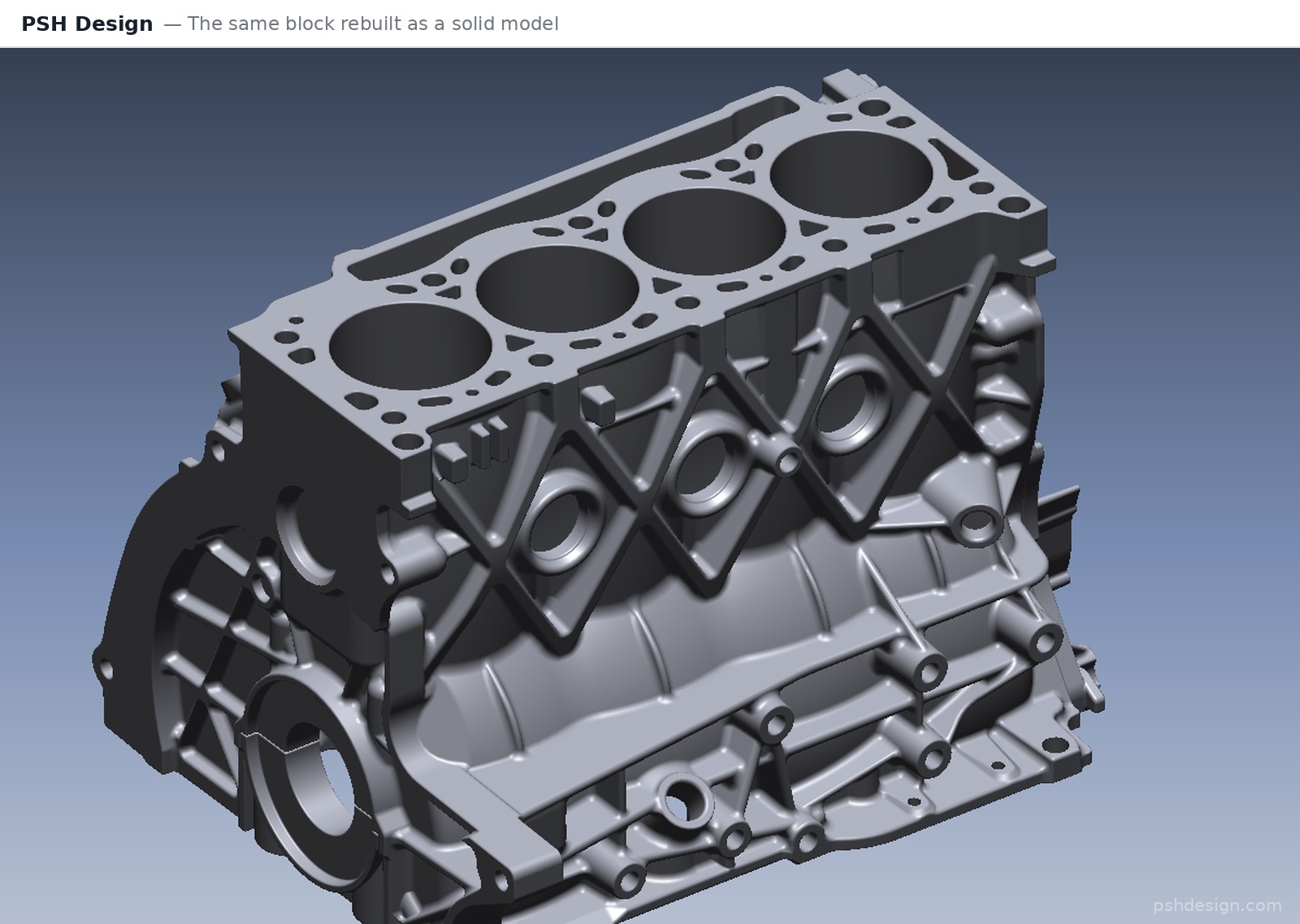
Three Mistakes We See in File Hand-offs
1. Not knowing a native file is on offer. Covered above — and the most expensive of the three, because the customer either rebuilds the history themselves from STEP or lives with a model nobody can edit.
2. Sending an STL and expecting an editable model back — without saying so. STL is an excellent starting point for reverse engineering. But without knowing which native system, what tolerance and which faces are functional, whoever rebuilds it has to guess.
3. Receiving STEP and using automatic feature recognition to “recover” the history. These tools are useful on simple parts. On complex ones they produce a feature tree that looks complete but carries hidden errors — which surface only when someone changes a dimension and the whole model fails with it, usually at the end customer.
Our reverse-engineering work runs to roughly 300 parts and 3,000 design hours a year, and has since 2009. A parametric rebuild typically sits within about 0.1 mm of the scan; a surface model that follows the scan as-built, within about 0.025 mm. Parts have run from a few millimetres to 80 metres.
Frequently Asked Questions
What is a CAD file?
A file that stores a 3D model or a 2D drawing made in computer-aided design software. Depending on the format, it holds only the geometry, or the geometry plus the build history, dimensions and tolerances.
What is the most common CAD file format?
For exchange between different CAD systems: STEP. For scan data and 3D printing: STL. The most common native format depends on the industry; SolidWorks is one of the most widely used among small and mid-sized manufacturers.
Should I use STEP or IGES?
STEP, in almost every case. IGES usually describes separate surfaces and often opens with gaps; STEP describes a closed solid, and AP242 also carries full semantic PMI.
Can an STL file be converted into an editable CAD model?
Yes, but not with one click. Automatic conversion gives you a surface wrapped around the mesh. An editable parametric model has to be rebuilt — functional faces, datums and nominal dimensions decided — by someone who understands what the part does. That is what reverse engineering is.
Can you build a CAD model from CMM data without a scan?
Yes. Section points measured on a CMM are enough for a full parametric model, as long as the sections cover every feature that matters. Send the exported point file, the inspection report and a note of where the sections were taken.
What file format does SolidWorks use?
.sldprt for parts, .sldasm for assemblies and .slddrw for drawings. SolidWorks desktop is built on the Parasolid kernel.
Is a STEP file editable?
Yes, within limits. A STEP file opens as geometry with no history: you can push and pull faces directly, but you cannot change one dimension and have the model update itself.
Reverse engineering at PSH Design
Written for you if you run a metrology, CMM or 3D-scanning business — or an engineering team — and need scan or CMM data rebuilt as parametric CAD, delivered native in the system your customer works in. Not for you if you need a quick mesh for 3D printing, or modelling with no engineering intent behind it. We do not take that work, and saying so saves both sides time.
Read in this order:
- You Bought the Scanner. Who Builds the CAD? — what usable CAD means to the people downstream, and the two rebuild methods.
- What CAD In-House Costs, What a Day Costs, and What Actually Grows a Lab — software, training, lead time, and the number most quotes leave out.
- Scaling Inspection Services with a Reverse Engineering Partner — how an inspection business adds CAD capacity through a partner rather than a department.
- Reverse Engineering Services — formats, tolerances, lead times and terms.
Then judge the work, not the words: send one part — a scan, a CMM report or a drawing — and we build it at our cost →
PSH Design
17+ years of CAS, Class A Surfacing, CAD and Reverse Engineering for Automotive, Aerospace, Medical and Industrial, to OEM standard.
Concept Design & CAS · Class A Surfacing · CAD Engineering · Reverse Engineering
Work of this kind is easier to judge than to describe.