クラスA入門 クラスA(または「Strak」)は、特に自動車設計において使用される用語です。自動車の美観部品の最終的な生産サーフェスデータを表します。「クラスA」という用語はしばしば誤解されますが、一般的にはサーフェスモデリングの「聖杯」と見なされています。これは、クラスAが最高レベルの[…]
クラスAモデリングの理解 / Understanding Class A Modeling

クラスA入門
クラスA(または「Strak」)は、特に自動車設計において使用される用語です。これは、車の外観部品の最終的な製造サーフェスデータを指します。
「クラスA」という用語はしばしば誤解されますが、一般的にはサーフェスモデリングの「聖杯」と見なされています。これは、最高レベルのサーフェス品質を実現するため、高度な自動車設計知識とサーフェスモデリングスキルが求められるためです。
クラスAは、設計プロセスにおける「職人技」の段階を表します。車両を表現する主要なサーフェス形状を作成することが、主要な設計作業です。しかし、美しいデザインが美しく製造された製品へと昇華されるのは、表面を完璧に仕上げ、フランジやパネルの隙間を設計する、緻密で繊細な職人技の賜物です。
クラスAとは?
クラスAのモデリングプロセスは、通常、スキャンしたクレイモデルまたはAliasモデルなど、完成したデザインから始まります。デザインが変更されることはないため、モデラーは最高品質基準のサーフェスを構築し、生産準備を整える時間を確保できます。
クラスAの課題は、以下の要件を両立させることです。
- 美観品質 – 連続性とハイライト
- エンジニアリング要件 – フランジとフィット
- 製造要件 – モデリング許容差
クラスAに必要な美観品質
基本要件:G0、G1、G2
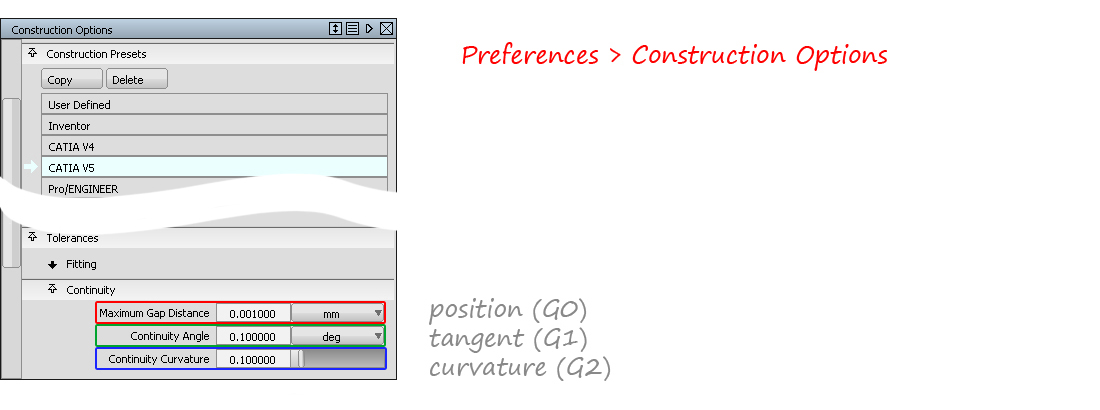
クラスAの基本要件は、あらゆる業界の製造品質のサーフェシングと同様、G0、G1、G2の連続性について厳密な許容差で構築することです。
Autodesk Aliasでは、モデリングを開始する前に適切なコンストラクション許容差(例:Catia V5)を使用することでこれを実現します。
以下のツール(複数可)を使用して、これらの条件が満たされていることを確認します。
- サーフェス編集 → ステッチ(モデル全体のG0ギャップをチェック)
- 評価 → サーフェス連続性(G0、G1、G2の個々の境界をチェック)
- 評価 → モデルチェック(モデル全体のG0、G1、G2、重複、小さなエッジなどをチェック)
許容差や連続性レベルには絶対的なルールがないことに注意することが重要です。クラスAモデラーのスキルと知識には、量産車で適切な品質を実現する設定を判断する能力と知識が不可欠です。
G3 Continuity
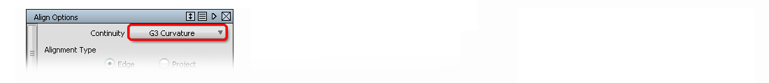
クラスAの美的品質とは、一般的に「完璧な」ハイライト反射と理解されています。これを実現するために、サーフェスパッチ全体にわたるG3 Continuity がよく使用されます。 G3 連続性は、Alias の以下のワークフローとツールで実現できます。
-
- サーフェス CV のダイレクトモデリングと、連続性のインタラクティブな評価を組み合わせたもの。
- オブジェクト編集 → 位置合わせ
- サーフェス CV のダイレクトモデリングと、連続性のインタラクティブな評価を組み合わせたもの。
- オブジェクト編集 → 位置合わせ
- サーフェスツール:フリーフォームブレンド、プロファイルブレンド、サーフェスフィレット、対称フィレット
- ブレンドカーブ
ハイライトの評価
「完璧なハイライト」は単一の評価では判断できません。複数の手法を組み合わせる必要があります。使用:
- 境界における連続性: 評価 → サーフェスの連続性
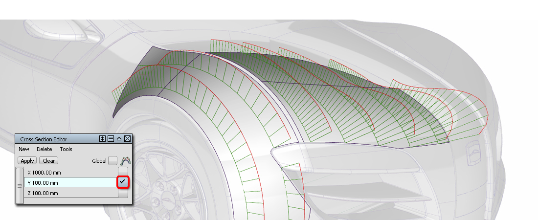
- 境界を越えた連続性: ロケーター → カーブの曲率とウィンドウ → クロスセクションエディタ
- 連続性フロー: 診断シェーディング → 等角と診断シェーディング → ライトトンネル
- ハイライトフロー: 診断シェーディング → サドルライン
- サーフェス品質: 診断シェーディング → 曲率評価
クラスAのエンジニアリング要件
これらは通常、自動車会社によって定義され、それぞれに詳細な基準が設けられています。設計の要素です。
例:
- 許容差は、A面、B面、C面などに固有のものです。
- 許容差は、外面、内面(木目の有無など)に固有のものです。
- 許容差は、メインブレンド、小さなフィレット、詳細なフィレットに固有のものです。
- スプリットライン、フランジ、パネルギャップ
この知識はテクニカルサーフェシングの専門分野であり、各社独自の専門知識であるため、ここで一般的な基準を示すことは不可能です。そのため、業界内で習得する必要があります。
クラスAモデリングを成功させる鍵
「サーフェスデータのレイアウトは、クラスAモデリングの鍵です。」


Introduction to Class-A
Class-A (or ‘Strak’) is a term used in specifically in automotive design. It describes the final production surface data for the aesthetic parts of the car.
The term ‘Class A’ is often misunderstood, but it’s generally seen as the ‘Holy Grail’ of surface modelling. This is because as it achieves the highest surface quality levels, and it demands a high level of automotive design knowledge as well as surface modelling skills.
Class A represents the ‘craftwork’ end of the design process. Creating the main surface shapes to describe the vehicle is the primary design activity. But the painstaking, detailed craftsmanship of perfecting those surfaces, designing flanges and panel gaps is what guarantees that a beautiful design turns into a beautifully manufactured product.
What is Class-A?
The Class-A modeling process typically starts with a fully developed design, either as a scanned clay model or an Alias model. Because the design isn’t changing, the modeler has the time to build surfaces to the highest quality standards, ready for production.
The challenge for Class-A is to combine the need for:
- Aesthetic Quality – Continuity and Highlights
- Engineering Requirements – Flanges and Fit
- Production Requirements – Modelling Tolerances
Aesthetic Quality required for Class-A
Baseline Requirements: G0, G1, G2
The baseline requirements for Class-A are the same as for production-quality surfacing in all industries: to build to tight tolerances for G0, G1 and G2 continuity.
In Autodesk Alias, this is achieved by using the right Construction Tolerances before you start modeling, for example, ‘Catia V5’.
And by checking that these have been achieved using one or more of the following tools:
- Surface Edit → Stitch (to check the whole model for G0 gaps)
- Evaluation → Surface Continuity ( to check individual boundaries for G0, G1, G2)
- Evaluation → Model Check (to check the whole model for G0, G1, G2, and duplicates, small edges, etc.)
It’s important to note that there are no absolute rules for tolerances or continuity levels. It is part of the skill and knowledge of the Class A modeler to be able to judge which settings will result in the right quality in the production car.
G3 Continuity
Class-A aesthetic quality is generally understood as being ‘perfect’ highlight reflections. G3 Continuity across the surface patches is often used to achieve this. G3 continuity can be achieved with the following workflows and tools in Alias:
-
- Direct Modelling of the surface CVs combined with an interactive evaluation of the continuity.
- Object Edit → Align
- Surface Tools: Freeform Blend, Profile Blend, Surface Fillet, Symmetric Fillet.
- Blend Curves
Evaluating Highlights
‘Perfect Highlights’ can’t be judged by a single evaluation, instead a combination of methods is used:
- Continuity at Boundaries: Evaluation → Surface Continuity
- Continuity across boundaries: Locators → Curve Curvature and Windows → Cross-Section Editor
- Continuity Flow: Diagnostic Shading → Iso-Angle and Diagnostic Shading → Light Tunnel.
- Highlight Flow: Diagnostic Shading → Saddle Lines
- Surface Quality: Diagnostic Shading → Curvature Evaluation
Engineering Requirements for Class-A
These are typically defined by an automotive company, with detailed standards for each element of the design.
For example:
- Tolerances are specific to A- surfaces, B-surfaces, C-surfaces, etc.
- Tolerances are specific for exterior surfaces, interiors (with and without grain for example).
- Tolerances are specific for main blends, smaller fillets, and detailed fillets.
- Split Lines, Flanges, and Panel gaps
It’s not possible to give a generalized set of standards here, as this knowledge is part of the profession of Technical Surfacing and the proprietary expertise of each company, and so needs to be learned within the industry.
The Key to Successful Class-A Modelling
“The layout of the surface data is the key to Class A modeling.” (Barry Kimball)
This means that the flow of CVs and Hulls and the flow of surface patches across the main surfaces and features of the car is the most important consideration for achieving Class A quality surface data.
This is the intention of the Golden Rules, to set out the right discipline for controlling surface quality. In particular:
- Bezier surfaces (for internal continuity/smoothness)
- G2/G3 continuity between surface patches
- Good CV Layout
- Working to the correct tolerances.
Reverse Engineering
Reverse Engineering is the process where a physical model (typically a clay) is scanned and then rebuilt as a NURBS model.
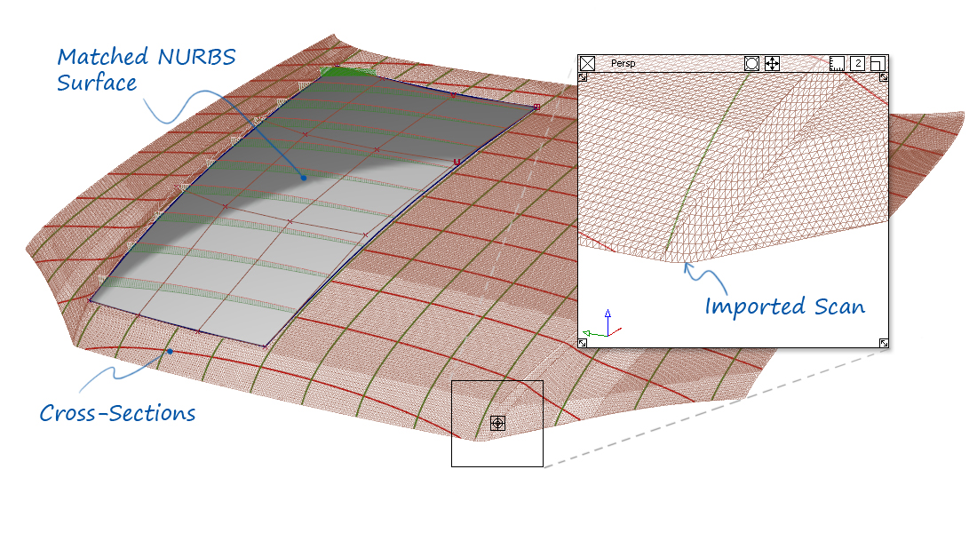
The modeler will be given a tolerance by which the NURBS data must match the scan. However, scan data will always have some imperfection, or ‘noise’, and they’re also may be imperfections in the clay model.
So the skill of the Reverse Engineer is to maintain the exact design character of the scan, whilst rejecting unintended imperfections.
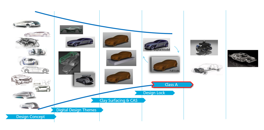
When is Class-A Applied?
Class-A modeling is slow and methodical. Therefore it is used on the final model iteration, once the design has been ‘locked’.
During Concept Modelling, the design changes are too rapid for strict Class-A standards to be applied. However, if Class-A principles are applied then the handover of data to Class-A modelers will be more effective.
Content retrieved from: https://www.aliasworkbench.com/theoryBuilders/TB11_class_a.htm.


Hotline

WhatsApp

Viber