Comparison of two different approaches of class-A surface creation and quality verification (ICEM Surf vs CATIA )
Comparison of two different approaches of class-A surface creation and quality verification
Jana Gulanová , Samo Lonek and Ladislav Gulan
(The Slovak University of Technology in Bratislava, Slovakia)
ABSTRACT
This paper focuses on a specific description of a class-A surface creation, mostly used in the process of vehicle body development. Since there is a huge effort to modernize the procedure, two approaches of a class-A surface creation are compared. The first one is quite old and well known and uses exclusively mathematical tools without any tree structure, hierarchy, or links. On the other hand, the second approach is closely linked to further procedure of components design using CAD tools. Both approaches are compared and broadly described using general objectives. Application of different procedures is demonstrated on a sport vehicle’s body development and its class-A surface creation.
1. Introduction
This paper briefly describes the procedure of Class-A surface modeling. It presents various quality conditions, which need to be accounted for during the development process. Next, two approaches of car body components development are compared. Introduction to this topic is given in [4], with a comprehensive description of tools of Generative Engineering Design (GED) methodology used for the development of surface-based components. GED method is presented in this paper, but mostly within the development of a class-A surface.
The presented project is an interesting meeting point of three fields – professional, research, and academic. The basics were taken from a workplace in the automotive company, which brought initial knowledge on a class-A surface creation. Later a research university workplace was working on specific examples to explain crucial points regarding the differences between the two approaches. Finally, all the results of investigated topics will soon be integrated into the pedagogical process.
2. Class-A surface development procedure
The procedure of vehicle body development within the automotive industry is divided into several phases. The basic workflow between conceptual design and pre-preliminary design is shown in Fig. 1. It is based on three subsequent design stages such as conceptual, preliminary and detailed. Each phase is important from a different point of view:
CAS – styling provides competitiveness and overall aesthetics;
STRAK – class-A surface development provides important qualities of car body visible surface;
CAD – for the development of the components, there are fulfilled several functional qualities.
STRAK is a German term for class-A surfacing. It has its origin in the shipbuilding industry, where STRAK- latte was used as a curve template [1,6]. In this paper, the term is mostly used to denote the development of class-A surface as a method or a special department in the auto- motive company, which models CAD quality surfaces using designated systems (such as Alias or ICEM Surf). In the following sections, we describe in detail some aspects of STRAK modeling which are then compared with a new method proposed as a part of GED. GED is demonstrated by CATIA and its specialized module ICEM Shape Design. ICEM Surf is an older and more developed system in comparison with Alias, which is the reason why it was investigated in the presented project.
2.1. Patches geometrical continuity
The quality of a class-A surface is usually driven by several specific tools. The crucial one is a tool for changing the order of a patch and the level of geometrical continuity between patches so that the quality is different. Modified- ability of control points’ row is affected as follows:
Figure 1. The flow of the designing process.
• Point continuity. Patches are connected with G0 continuity, so there is an edge between them. In the case of modification, only the edging row of control points is affected. The higher-order patches provide infinite solutions to the overall shape. (Fig. 2(b))
• Tangent continuity. Patches are connected with G1 continuity, the connection is smooth. In the case of modification, two rows of control points are affected. (Fig. 2(c))
• Curvature continuity. Patches are connected with G2 continuity, the connection is smooth. In the case of modification, three rows of control points are affected. (Fig. 2(d))
• Torsion continuity. Patches are connected with G3 continuity, the connection is smooth. In the case of modification, four rows of control points are affected. (Fig. 2(e))
Figure 2. Two patches of the same order are connected using the various levels of continuity: (a) no connection, (b) point continuity, (c) tangent continuity, (d) curvature continuity, (e) torsion continuity.
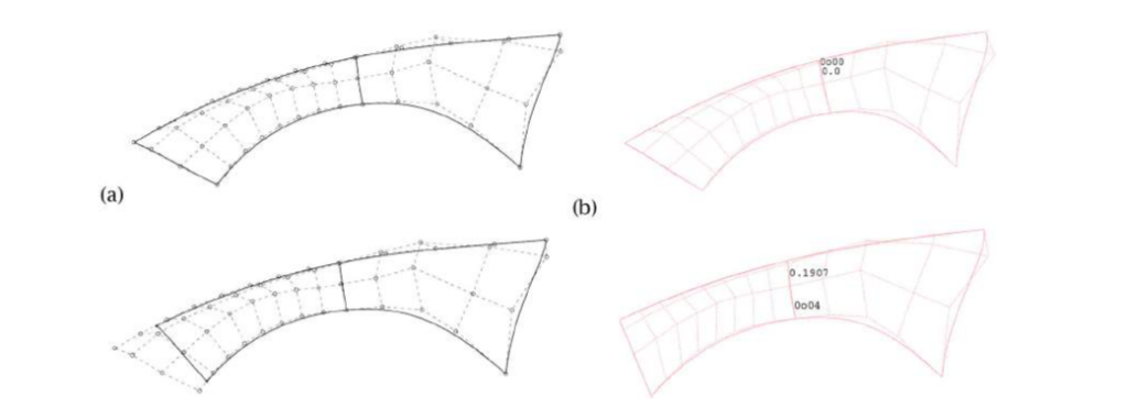
The row of control points represents an edge of control polygon connecting two or more control points along with one parameter of a surface, either u or v. This modeling mathematics is behind any class-A procedure. Whenever the CAD of a class-A surface is created by using a specialized system (Alias, ICEM Surf), or using a general CAD system (CATIA), there needs to be patched having a specific order to achieve appropriate quality. [5] When the patches are connected fulfilling a specific continuity level, it is important to acquire the same order of both patches in one direction. In ICEM Surf, when patches are split by boundary curves, the control polygon is possible to become deformed. This happens especially if the boundary curve traverses the control polygon from one row to another and crosses an edge. Then, geometrical continuity is disrupted and surrounding patches need to have renewed matching. The re-creation of the control polygon is shown in Fig. 3. In CATIA, both the original patch and a new split patch having the same control polygon are stored.
Figure 3. Split of the patch by curve crossing control polygon edge in (a) CATIA, (b) ICEM Surf.
STRAK procedure, or a class-A surface modeling, is divided into several steps regarding the level of continuity. It is described in [4]. Based on such a procedure, there was created a class-A surface of sports vehicles as the next step with respect to the previous work. Stages are shown in Fig. 4. The first step is shown in Fig. 4(a). It is styling from the designer known as CAS. Subsequently, a cloud of points of scanned clay model taken from real size model made by CNC milling machine is shown in Fig. 4(b). And finally, a complete class-A surface of the whole car body is shown in Fig. 4(c). The complete CAD of a class-A surface was made in the specialized module of CATIA called ICEM Shape Design. Modification of a patch can lead to the displacement of some rows of another patch. If the procedure of GED is obeyed, all the affected patches are usually modified with geometrical continuity preserved. In the case of using ICEM Surf, an automatic modification is impossible. All the affected changes must be performed manually. There are no hierarchical links between patches in ICEM Surf.
3. Technical aspects of two modeling approaches
STRAK is known in the automotive industry as a middle stage between the styling creation and the development of the components as is shown in Fig. 1. Its goal is to create class-A surfaces using a specific mathematical description such as the Beziér curve or B-spline. Class-A surface is an overall visible surface of the vehicle body.
Firstly, a virtual model of the vehicle is created in CAS software or by using CAS tools based on the concept package. Package includes occupant, cargo, powertrain, and tires accommodation and might be linked to design sketches. If the model meets all the requirements, it is consequently used to build several clay models in original size by using large-scale CNC milling machines. Clay models are only modified in the sense of some details in the eyes of the designer. One of the clay models is then chosen as final and 3D scanned. The 3D scan in form of a cloud of points further serves as the input for class-A surfaces creation. For such purposes, patches are used. Their connection is based on the level of continuity. Afterward, patches are blended and filleted. The complete class-A surface consisting of dozens of patches is then frozen and transformed to CAD. It means an output of STRAK system, such as ICEM Surf, represents the input to CAD systems such as CATIA or NX.
The described approach is illustrated in Fig. 5 (a).In contrast to the described STRAK procedure, there is another approach, which misses the particular STRAK phase. It is shown in Fig. 5 (b). System CATIA enables a separate module using ICEM Surf tools. The clay model in form of a Cloud of Points is directly inserted into CAD.
Figure 4. (a) CAS, (b) scanned clay mode data (c) class A surface
Figure 5. (a) Development approach involving STRAK step, (b) Development approach missing STRAK → GED.
The main advantage is the possibility to generate modified components in case of a class-A surface change. The reason lies in the input of the development phase. There are separate patches using active connections in form of a blend or a fillet, which are active all the time during the detailed design. In case of modification made within the class-A surface patches, all the affected components are remodeled automatically, with the minimal human intervention [3,4]. Such an advantage is not possible in the case of using a specific STRAK procedure, since all the surfaces are frozen in one group and inserted into the CAD system. A broader comparison of two different approaches is presented in the following section. Class-A surface creation within the CATIA ICEM module is described in [4], similarly to the following points, and is also shown in Fig. 6:
• CATIA ICEM module loads styling data in the form of a Cloud of Points. Patches are connected with the lower class of continuity, such as G0 or G1, in order to form an intermediate model with sharp connections.
• Patches are divided into sections, higher continuity should be fulfilled within a specific section first and later lower level of continuity should be fulfilled between sections.
• Interfacing curves (or boundaries, usually isoparametric curves) are defined on the patches with respect to the shape of the future output model. During any following modification, boundaries are generated automatically.
Figure 6. Creation of patches of one section using CATIA.
Connecting surfaces of patches are created with boundaries derived from interfacing curves. Important is a higher class of continuity, such as G2, G3, or higher, to achieve smooth output surfaces.The difference of previously described procedure against the procedure of ICEM Surf lies in the necessity of connecting- ing patches and procedure is as follows, and is also shown in Fig. 7:
• ICEM Surf loads styling data in the form of a Cloud of Points.
• Patches are connected with the lower class of continuity, such as G0 or G1, to form an intermediate model with sharp connections.
Figure 7. Creation of patches of one section using ICEM Surf.
• Patches are divided into sections; higher continuity should be fulfilled within a specific section first and later lower level of continuity should be fulfilled between sections.
• Apart from CATIA, here the patches within a section are matched manually to be precise and between sections are created connecting surfaces such as blends or fillets.
4. Learning aspects of two modeling approaches
Learning aspects described in this section are based on the experience from the pedagogical process at the Institute of Transport Technology and Engineering Design, Faculty of Mechanical Engineering, the Slovak University of Technology in Bratislava. Students start with basic knowledge of CAD, and later they learn how to use a specific procedure of shape modeling. It is learned within the subject of components engineering design, what is suitable for functional features creation, and other engineering steps regarding design. It is represented by the Generative Shape Design module in CATIA. Such a procedure is not suitable for a class-A surface creation, since it does not utilize freeform surfaces. On the other hand, learning engineering design using CAD provides sufficient basics of surface modeling in the general context.
A comparison of two modeling approaches may be performed by considering various aspects. One of them is the learning process. An approximate learning curve is shown in Fig. 8. It is approximate because there were no specific observations focused on the proficiency of students. It is only based on the experience from studies of CAD systems at the Slovak University of Technology.
Learning aspects are considered within three different design procedures:
1. CATIA – used without any advanced knowledge as a similar tool as ICEM Surf;
2. ICEM Surf;
3. CATIA GED – CATIA with GED method enabling automatic modifications.
The learning curve consists of the following three stages. Firstly, it is necessary to acquire the basics of surface modeling theory, such as freeform curves and surfaces, control polygon, continuity levels, isoparametric curves, etc. Secondly, users explore tools’ possibilities to create or modify curves or surfaces. The use of CATIA GED is conditioned by a wider knowledge of GED tools; hence the second stage is slower in comparison to others. Thirdly, users achieve the highest proficiency, which is different for each procedure
Figure 8. A learning curve comparing three different procedures.
Figure 9. Explanation of highlight analysis [2].
.
5. Professional process of class-A surface creation
The real development process of class-A surfaces of one specific vehicle lasts for approximately 2 years. There are always several variants and dozens of engineers work- ing on their development. These variants are merged gradually into one final project. The period reserved for the presented project was only 4 months, during which a class-A surface was created using two different approaches. There was only one engineer working on a specific task at a time.
Geometrical continuity of connections between patches is described in section 2.1. Tolerances of specific continuity levels are described in Tab. 1.
Table 1. Limiting tolerances of continuity levels used in a professional process.
It was proven to fulfill the required continuity level without deviation. These values only have an informative character, since the outcome needs to preserve the design intent. In particular, highlight analyses are used for such a purpose.
With the highlight diagnosis lines of equal lightness are displayed on surfaces. These lines connect the surface points, where the angle of incidence of the light is constant; and are called “Isophotes”. The brightest reflection occurs at an angle of incidence equal to 90°. [2]
For the computation of the isophotes, all points in which the surface normal has the same direction will be determined. The angle between light direction and surface normal is constant. [2]
The course of highlight lines illustrates – as well as reflection lines – the shape of the surface and the quality of surface matchings. The flow of the highlight lines should form a uniform family of lines. Gradually widen- ing or narrowing, but in general, never pinching in and out. [2] Even though there are some torsional geometry continuities between patches achieving limiting deviation, the overall design may not meet the designer’s intention. This is the main reason for the application of highlight analysis. The geometry of patches is changed by modification of control points’ positions to achieve the desired light reflection. It is extremely time-consuming since every modification of the patch forces to modify all surrounding patches.
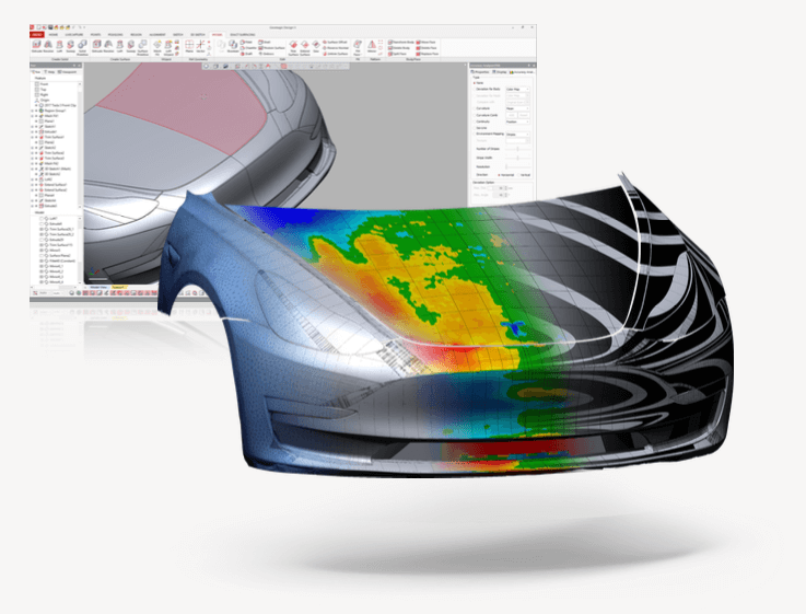
Highlight diagnosis applied on models of both class-A surface systems is presented in Fig. 10. The diagnoses are only demonstrative since the presented project was not elaborated in a broader cooperation with designers.
Figure 10. Comparison of highlight diagnoses in ICEM Surf and CATIA.
6. Comparison of two different modeling approaches
Comparison is shown in Tab. 2, where similar aspects are compared in each row :
Table 2. Two different approaches of a class-A surface development process compared within similar objectives.
Figure 11. A cylinder was created using different mathematical descriptions of surfaces in the ICEM Surf: (a) Beziér curve; (b) B-spline; (c) NURBS.
7. Conclusion
The presented paper briefly explains crucial aspects of two different approaches to class-A surface creation and modification. They are described regarding various aspects such as geometry basics, learning process, etc. Even though it looks like there are significant advantages of the new method using module directly in a CAD system, it is difficult to involve it in a real development process. In practice, there are no projects known to be using CAD systems for class-A surface development. That is one of the reasons for Laboratory of Generative Engineering Design to work on creating a new methodology, which saves time while respecting a high-quality standard [3,4]. Class-A surfaces are possible to be created using the module in CATIA, but this tool should be developed to involve all the advantages of separate software. The most important one is to achieve the best resulting quality.
( The source : Jana Gulanová / http://orcid.org/0000-0003-2041-1993 )
