Three Reverse Engineering Jobs, Start to Finish: a Prototype, a Worn Part, and a Product Reborn From Its Mold
Our articles on reverse engineering have covered what it costs, whether to build the capability in-house, and who builds the model after the scan. This one stops talking and shows. Three real jobs that recently went through the studio — three completely different starting points, one discipline. Published with the customers’ permission; the default at PSH is NDA on every job, including the ones we are proud of.
Part one: an unfinished prototype — capturing the shape and the intent
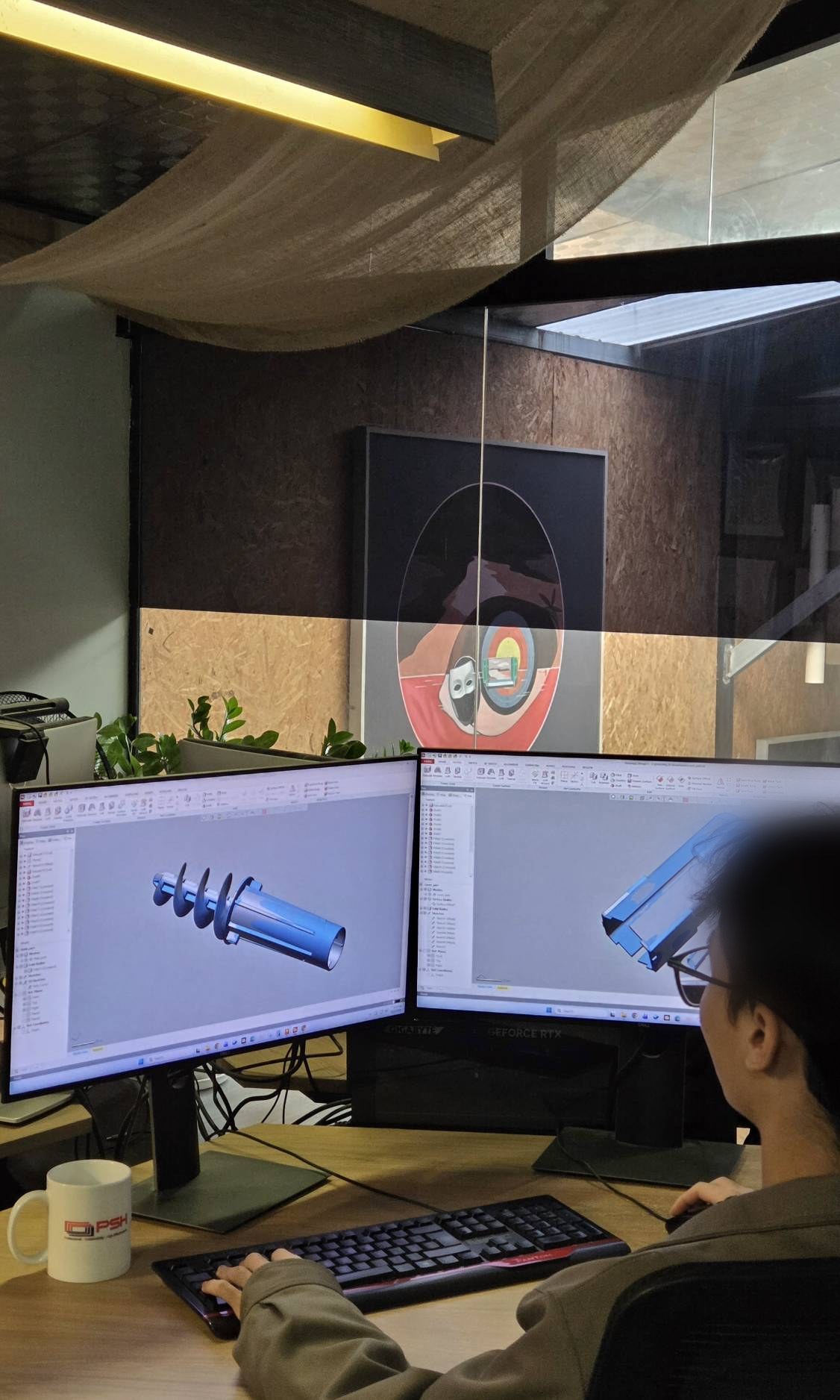
The part arrived as a two-piece molded plastic assembly: a self-drilling helical anchor and its cap. Not an old component that needed digitizing — a new product, not yet finalized, built by the customer to prove an idea. The brief was not “copy this accurately.” It was: extract the true geometry and the design intent behind it, then carry both forward to a design that meets a stricter set of requirements.
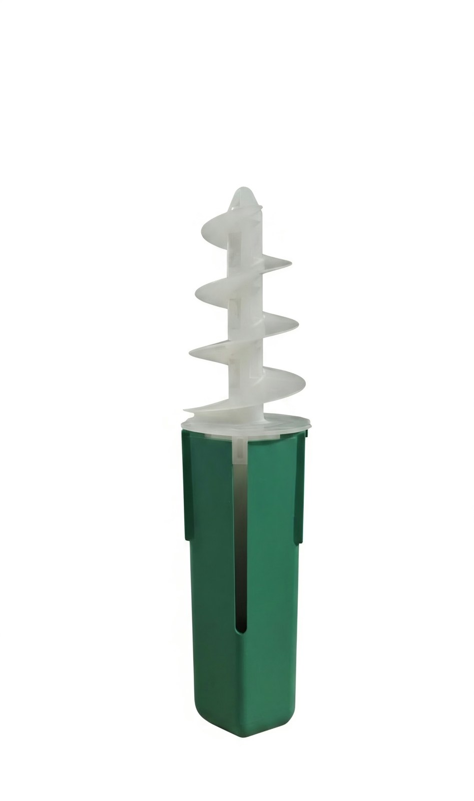
Capturing the shape is the easy half. The half that needs an engineer is reading which features are intent and which are artifacts of a prototype: the pitch of the helix is design; the sink marks on the body are a consequence of how the sample was made. One edge is sharp because it has to cut material; another is sharp only because the trial tooling was rough. An automated scan-to-CAD conversion preserves both kinds equally — which is exactly how a model can pass the deviation check and still fail in production.
The customer’s new requirements were tighter in two places that no scanner can see: the assembly clearances between the parts, and working reliability — the mechanism had to function correctly, every time.
Rebuilt as parametric CAD — 32 hours
We rebuilt the assembly as native SolidWorks models with a real feature tree: 32 hours of modeling. Why parametric rather than an as-built NURBS skin? Because the next step was change. A clearance that must be tuned should be one dimension; a helix that must be adjusted should be one parameter — not a rebuild from scratch.
Optimize, print, test — two rounds and done
Optimization against the new requirements took another 12 hours on top of the parametric rebuild. We 3D-printed the design, assembled it, ran it, fed what we learned back into the model, and printed once more. Two rounds were enough: the mechanism worked reliably and the clearances met the new specification. The changes went into the final data set — 44 hours of modeling in total, plus two print-and-test loops.
Part two: a worn excavator component with no drawings — 48 hours
The second job came from the opposite direction. A major Japanese construction-equipment manufacturer needed a bucket component whose original drawings had been lost years ago. The only thing left was the physical part — worn by years of work.
With the prototype in part one, the measured surface was not the truth, because the sample was unfinished. Here the measured surface was not the truth either — for the opposite reason: it was the original design plus twenty years of wear. The scan is only the starting point.
Recovering the original meant reading the part the way its designer would: a worn face read from its less-worn mirror twin; a deformed radius inferred from the design logic of the rest of the part; mating dimensions checked against the machine interface it once bolted to. No software does this on its own. The result is nominal geometry — the component as it left the drawing board, not as it left the job site.
Then the second half of the brief: the customer did not want a replica of a twenty-year-old part. They wanted it to fit the machines they sell today. This is what the nominal model is for: once it exists, the fit can be tested digitally against the current machine before any metal is cut — and where an interface has moved on, the model becomes the basis for an adapter instead of a redesign. We adjusted the design to the current machine’s mounting interface. One legacy component, back in the catalog — instead of an entire assembly replaced. The whole job, recovery and adaptation, took 48 hours.
Part three: a 10-liter can reborn from its mold — 40 hours, one week
The third job inverted the direction entirely. A North American mold maker wanted to recreate a product — a 10-liter can — whose design data no longer existed, or had never existed digitally at all. What they still had was the old mold: two halves of it. They scanned both halves themselves and sent us the data.
The obvious shortcut would be to machine new mold halves directly from the scans of the old ones. Nobody serious would sign off on that: a cavity wears like any other working surface, and cutting fresh steel from its scan means faithfully reproducing every year of that wear — an old cavity is no guarantee of a good new product. The only safe path runs through the product itself.
A mold cavity is the negative of the product. From the scans of the two cavity halves we rebuilt the product — the can as it was designed, not as the cavity had worn. We updated a handful of details to the customer’s current requirements. Then we ran the whole logic in reverse: split the new product model into new cavity and core halves.
Delivered after roughly 40 working hours, inside one week: a completely new data set — the complete 10-liter can model, plus new cavity and core ready for machining. The customer’s old mold never had a digital original. Now it has one, and the data is younger than the steel.
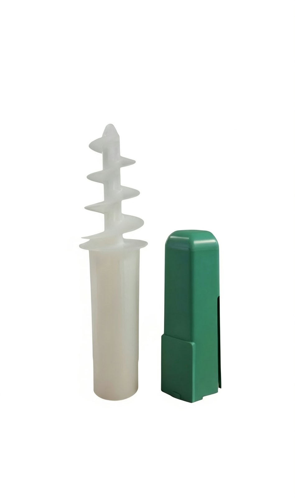
There are no photos of the second and third jobs in this article. That is not an omission — it is the point. Discretion is part of the service.
Why this kind of work keeps growing
A component that has served in a customer’s machine for years is that customer’s asset. The serious construction-equipment makers are adapting their designs so that those assets are not wasted — and so their customers have more options than “replace the whole assembly.” Mold shops face the same problem from the other side: the hardware outlives its data. The steel is still standing in the shop long after the drawings have been lost through three changes of management.
And the parts that are still in service are not finished either: a product that works in the field accumulates improvement requests the day it ships. Reverse engineering is how a physical product that has outrun its data gets a CAD basis to be improved on at all.
Reverse engineering, done properly, is the tool behind that strategy. It keeps the life of a product longer than the life of its paperwork — and with every year that passes, this kind of restoration becomes more useful, not less.
Three starting points, one question
Look again at what the three jobs had in common. The defect was always the same thing wearing different clothes: time. A prototype is ahead of its final form; a worn component and a worn cavity are behind theirs. In every case the physical object in your hand is not the design — and nobody can promise you that an old cavity still molds a good product, or that an old part still fits a new machine, until someone rebuilds the correct design and checks.
An unfinished prototype: the truth is the intent ahead of the part. A worn component: the truth is the design behind the part. A mold cavity: the truth is a product that was never drawn. Three times, the real question was never “can you scan it?” It was “what is the correct design?” — and answering that is engineering work, not a software feature.
What each customer received is the same in kind: a native model with a real feature tree — SolidWorks for the anchor; the customer’s own CAD system for the others — drawings to their standard, and a design that had been verified: by a working printed prototype, by the mounting interface of a real machine, or by a brand-new pair of mold halves. Open the file and keep working, as if your own team had built it.
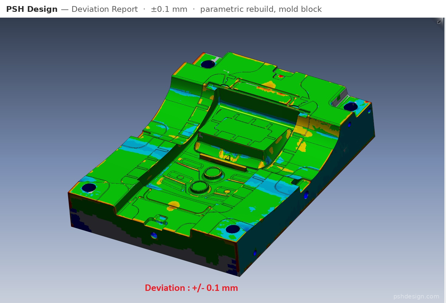
This is exactly what you receive when you send your first part — and the first part is at our cost. Send one part and see the data, or read how the reverse engineering service runs.
Questions we are asked
How is reverse engineering an unfinished prototype different from reverse engineering an old part?
With a new prototype you separate design intent from the artifacts of the sample. With an old part you separate the original design from wear. It is the same skill — reading backward from the physical object to the correct design — and no software does it unattended.
The part is worn. Can you rebuild it to its original dimensions?
Yes. Worn faces are read from less-worn symmetric features, deformed details are inferred from the design logic of the part, and mating dimensions are checked against the machine it fits. The result is nominal geometry, not a copy of the wear. The excavator component above took 48 hours.
We only have the mold, not the product. Can you rebuild the product?
Yes. The cavity is the negative of the product. From scans of the mold halves we rebuild the product model, update what needs updating, and can split new cavity and core halves from the new model. The 10-liter can above took about 40 hours, delivered inside a week — product model plus new mold halves.
Our drawings are lost. What do you need from us?
The physical part or a scan of it, the machine or assembly it fits into, and your drawing standard. That is enough to start.
Can you optimize the design during reverse engineering, not just copy it?
Yes, if the model is built parametric from the start. The anchor above was 32 hours of rebuild plus 12 hours of optimization against new clearance and reliability requirements.
Is testing with a 3D print reliable enough?
For fit and mechanism function, yes. Two print rounds settled the design above. Final material behavior belongs to the customer’s trial tooling.
How long does this take?
The three real jobs here: 44 hours, 48 hours, and about 40 hours. Every quote goes out within 24 hours of seeing your data.
The product is unreleased. How is confidentiality handled?
Every job runs under NDA by default — not on request, and not as an extra step you have to ask for. This article exists because the customers gave permission; the default is that nothing leaves PSH.
PSH Design
17+ years of CAS, Class A Surfacing, CAD and Reverse Engineering for Automotive, Aerospace, Medical and Industrial, to OEM standard.
Concept Design & CAS · Class A Surfacing · CAD Engineering · Reverse Engineering
Work of this kind is easier to judge than to describe.