A scan is a surface, not a model. Two rebuild methods, the deviation figures behind each, and why the delivery format decides whether the work gets used.
You Bought the Scanner. Who Builds the CAD?
日本語版はこちら → · Deutsche Version →
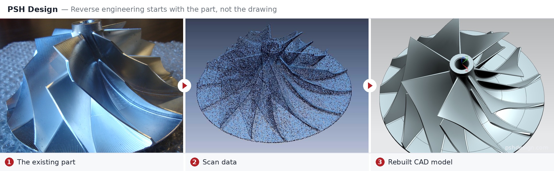
A scan is a point cloud or a triangle mesh. It records the surface of a part. It does not record the design intent that produced that surface. Rebuilding it as parametric CAD with a live feature tree is a separate trade, with its own methods and its own numbers — and the right number depends on what the part is for.
A customer sends a part in for measurement. The report goes out. Then they ask:
“While you’re at it — can you give us the CAD too?”
That question is a fork, and the answer to it decides whether the scanner in the next room earns once per job or twice.
What follows is what the second answer actually requires: what “usable CAD” means to each person downstream, the two rebuild methods and what each one holds, why dedicated software does not settle it, and why the delivery format decides whether any of it gets used. The commercial side — what this capability costs to build in-house, and what a day of lead time is worth — is in a separate article, linked at the end.
The Scan Is Not the Deliverable
Fifteen years ago, scanning the part was the hard step. Today it is routine. A modern structured-light scanner produces a usable mesh of a mid-size casting in minutes rather than hours, and a well-equipped lab does this every day — in Michigan as in Stuttgart.
The bottleneck moved. It is no longer in capturing the data. It is in turning that data into something the person at the other end can use.
A mesh can be machined from, at a push, and some CAM systems will generate toolpaths directly from one. What a mesh will not do is change. Nobody adjusts a wall thickness in a triangle mesh. Nobody applies GD&T to one. A mesh is a geometric record — accurate, faithful, and fixed. It records the part as it is, including the wear, the warp, the mold mismatch. It carries no statement of what the part was supposed to be.
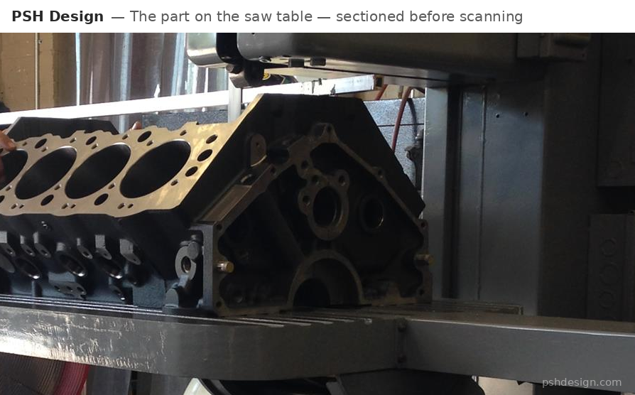
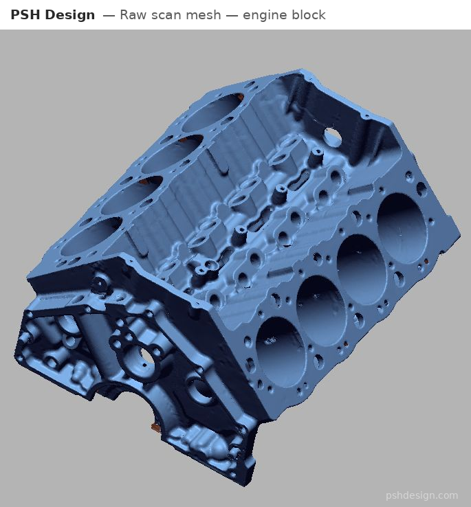
Which is why the question at the top of this article gets asked in every inspection lab that owns a scanner, on both sides of the Atlantic. Answer it yes, and the volume of work in the lab goes up without buying a single piece of equipment. Answer it no, and the customer goes looking — and next time, the person they find will be the one standing closer to the part than you are.
What “Usable CAD” Means to the Person Downstream
“CAD” is not one standard. It is three, depending on who receives the file.
The mold shop needs a watertight solid: no gaps, no sliver faces, correct draft, and a fillet that reads as a fillet rather than a freeform patch shaped like one.
The CNC programmer needs clean, continuous surfaces. A solid auto-converted from a mesh often carries thousands of tiny faces; depending on the toolpath strategy and the finish required, that can range from a nuisance to a re-quote. Either way the person who finds out is the programmer, after the job has been priced.
The design engineer at the end customer needs an editable feature tree. They are not opening the file to look at it. They are opening it to take a bore from 40 to 42, move a rib, change a wall thickness. A history-free solid — a “dumb solid” in shop language — can still be modified with direct editing tools, and modern CAD does this well. But direct editing changes geometry; it does not change intent. Nobody can pull a dimension out of a face that was never dimensioned.
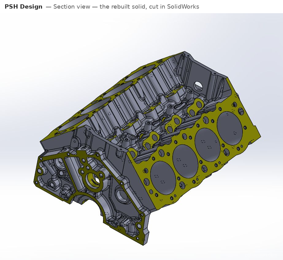
An automated mesh-to-solid conversion can satisfy the first. It may or may not satisfy the second. It does not address the third at all.
What is worth noticing is that all three groups use the same word, and none of them says which definition they mean. A good share of the arguments about rebuild quality start there rather than in the tolerance.
Two Rebuild Methods, Two Different Numbers
There are two ways to rebuild a part from scan data, and they produce two different deviation figures. Both figures below are mean deviation to the scan data, from our own work — they are internal observations, not an industry standard. No standard specifies deviation for these methods, for reasons the rest of this section explains.
| Method | Mean deviation to scan data | What you get |
|---|---|---|
| As-built NURBS | ~0.025 mm (a clean, accurate scan can reach 0.01 mm) | A faithful surface copy. No feature tree. Not parametrically editable. |
| Parametric rebuild | ~0.1–0.2 mm, depending on input scan quality and the condition of the scanned part | A model with a feature tree and nominal dimensions. Editable. |
Most people read that table and reach for the smaller number. For a part that is going back into manufacture, that is often the wrong instinct.
The 0.1–0.2 mm figure is larger, and on most industrial parts it is larger on purpose.
First, why it is a range rather than a number. The range does not reflect uncertainty on the modeler’s part. It reflects two things outside the modeler’s control:
- Input scan quality. Holes, noise, occluded regions the scanner could not reach, leftover fixture geometry — each one forces the modeler to infer a little further.
- The condition of the part itself. A component that is worn, warped, mold-mismatched or has been hand-corrected on the shop floor has already departed from nominal before anyone picked up a scanner.
A real industrial part — a used casting, a worn gear, a mold half that has been hand-dressed three times — has a real surface that includes its defects. Copying that surface to 0.025 mm means faithfully copying those defects and then manufacturing from them.
Put the question the other way round:
Why reproduce deviations with high precision, and then build to them?
A parametric rebuild does something different. It looks at the distorted bore and proposes: this was a Ø40 H7 bore. It looks at the slightly bowed face and proposes: this was flat, perpendicular to datum A. That is a judgment about design intent, and it can be wrong. A larger deviation figure does not by itself prove the judgment was right; it only means the model is not following the scan. Whether the judgment is correct is settled by the drawing if one exists, by the function of the mating parts, and by the customer confirming it — not by the color map.
That is exactly why we ask what the part is for before deciding how to rebuild it, rather than defaulting to the tighter number because it reads better in a quotation.
When as-built NURBS is the right call: wear comparison · deviation analysis and distortion checks after heat treatment or molding · parts with no design intent to recover, such as genuinely freeform or hand-sculpted shapes · archival and legal documentation.
A deviation figure is not usable until you say what it measures
This is what a measurement professional notices first, and it is where numbers are most often quoted loosely.
Both figures above are deviation between the model and the scan data — not between the model and the physical part. The scan carries its own error: instrument error, registration error where multiple scans are stitched, noise on poorly reflective surfaces, and regions never captured. A model that follows the scan closely still sits at whatever distance the scan sits from the part. Those two error sources combine; how they combine depends on the case, and they are not simply added together.
The figure also needs a definition before it can be compared across suppliers:
- Mean, maximum, or RMS? On the same model these can differ substantially.
- Measured over what? The whole surface, or only functionally significant surfaces? Including or excluding data-poor regions and flash?
- Aligned how? Global best-fit, or aligned to the part’s datum reference frame? The two give different results on the same pair of datasets.
A lab comparing two quotes should ask all three. If the supplier answers immediately, the figure means something. If the answer is only a good-looking number with no method attached, it is marketing copy rather than a specification.
Ours, stated plainly: the figures above are mean deviation. Maximum deviation depends on the part and the scan, and we give it on your specific part when we quote — a single headline figure for it would be dishonest.
Three bands, one part
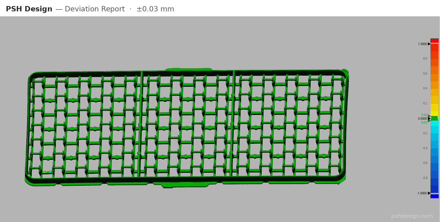
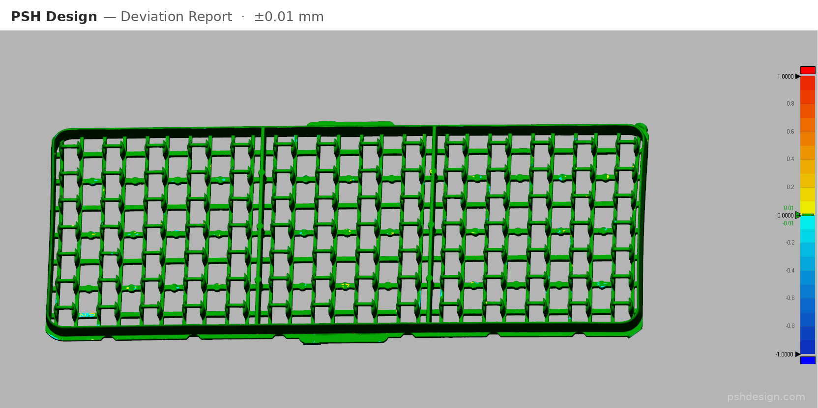
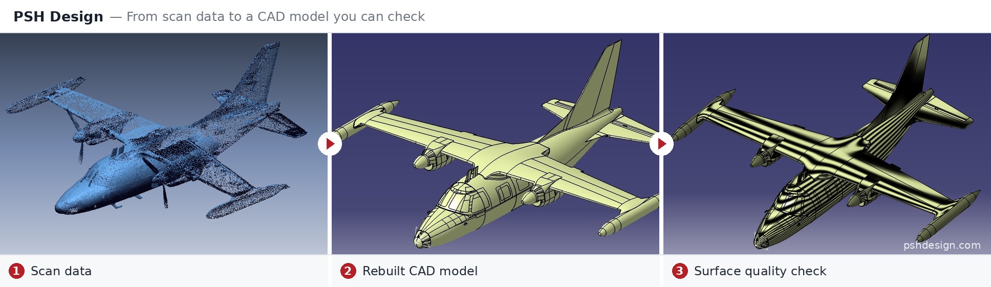
The same part, the same scan, the same model — checked at three band widths. Widen the band and the surface goes uniformly green; tighten it and you can watch the outliers appear.
| Band | Points inside |
|---|---|
| ±0.03 mm | 99.9% |
| ±0.02 mm | 99.4% |
| ±0.01 mm | over 98% |
That is coverage at a named band, as-built NURBS, measured across the full scanned surface. A single headline number would have hidden the shape of that distribution. This is the distribution.
The points outside the tightest band are not scattered at random. They sit where they always sit — on edges, in corners, and down in the pockets where the scanner sees at a glancing angle. Anyone who has run a scanner already expected that.
And this is a best case. A rigid part and a clean scan make it possible; a worn casting reaches neither figure, for physical reasons rather than for want of care.
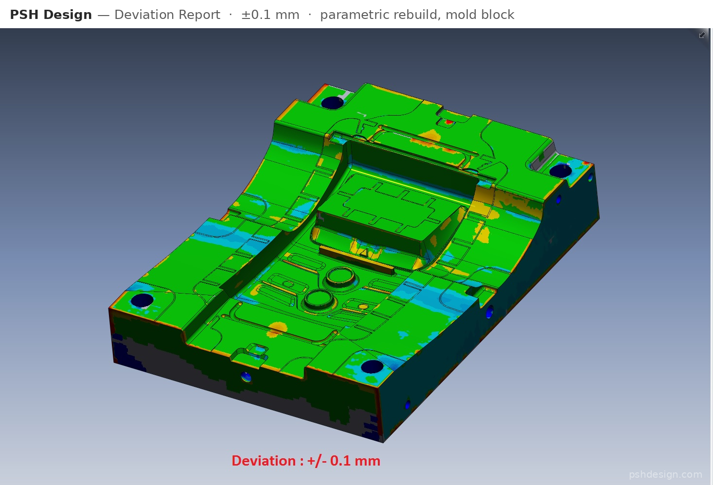
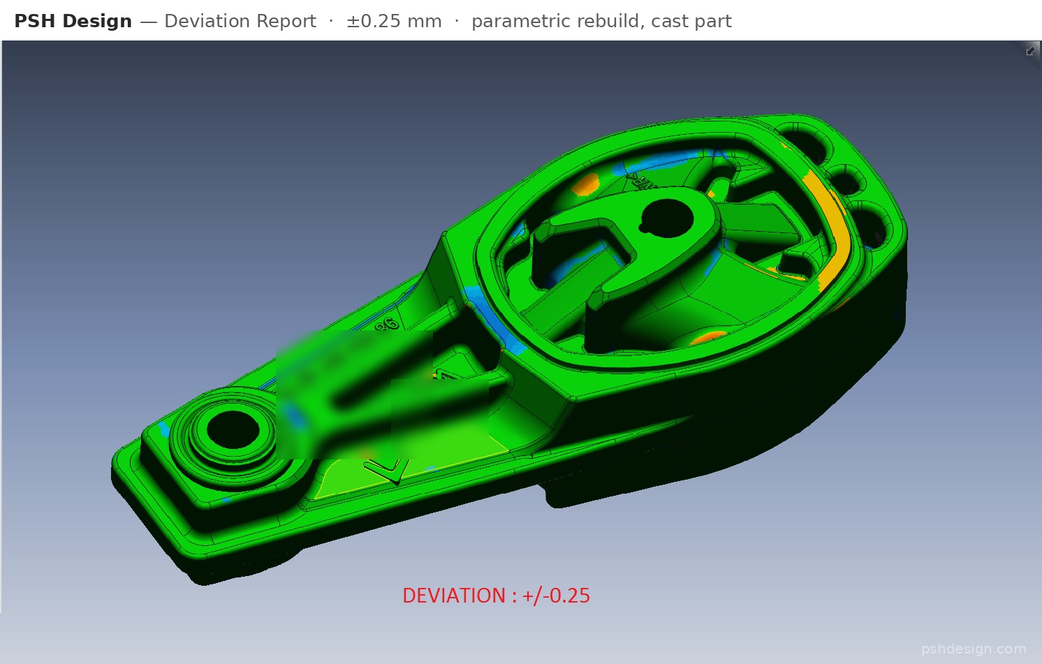
Two parametric rebuilds for contrast: a mold block checked at ±0.1 mm, and a casting checked at ±0.25 mm. The yellow along the edges and the blue in the deep pockets is the parametric model following nominal geometry rather than the as-found surface. A report that came back uniformly green on parts like these would mean the model had copied the condition instead of proposing the design.
Why Dedicated Software Is Not the Answer Either
There is a common argument: general CAD is not enough for reverse engineering, you need dedicated software.
The first half is right. The second half does not go far enough.
Dedicated software exists and it is good. Geomagic Design X (now Hexagon), PolyWorks|Modeler (InnovMetric) and QUICKSURFACE (KVS, Cambridge) are the three names most often heard in this work.
And the major CAD systems all handle scan data now, by three different mechanisms that buyers are rarely told apart:
- Built into the seat: SolidWorks has ScanTo3D, reading meshes (STL, PLY, OBJ) and point clouds (XYZ, TXT, ASC) directly.
- Paid separately: Creo needs the Reverse Engineering Extension. CATIA V5 uses the Digitized Shape Editor and Quick Surface Reconstruction workbenches. Inventor uses the Mesh Enabler add-in.
- Core capability, no conversion: NX and Solid Edge use Convergent Modeling, working directly on facet bodies without converting mesh to surfaces first.
The tooling is not the barrier.
The problem is elsewhere. Every one of those packages has a set of automatic commands: auto-segment, auto-surface, auto-detect features. Click, wait, and a solid appears. The deviation check returns a green map. It looks finished.
A green deviation map means the model follows the scan. It does not mean the model meets the functional tolerances of the part, and it says nothing at all about the things that break downstream:
- Two adjoining faces that are nearly tangent but not quite — which may leave a visible machining mark, depending on the toolpath and the finish
- A fillet built as a freeform patch instead of a fillet feature — the shop cannot vary it, and CAM does not recognize it as a fillet
- A bore that is not round, because it was built to follow the distorted bore in the scan instead of being recognized as a bore
- No datum reference frame, because nobody decided which face is A
All of these can fall inside the deviation band. All of them return a green map. And all of them surface later — at the mold shop, at the machine, or six months on at the end customer’s engineer’s desk.
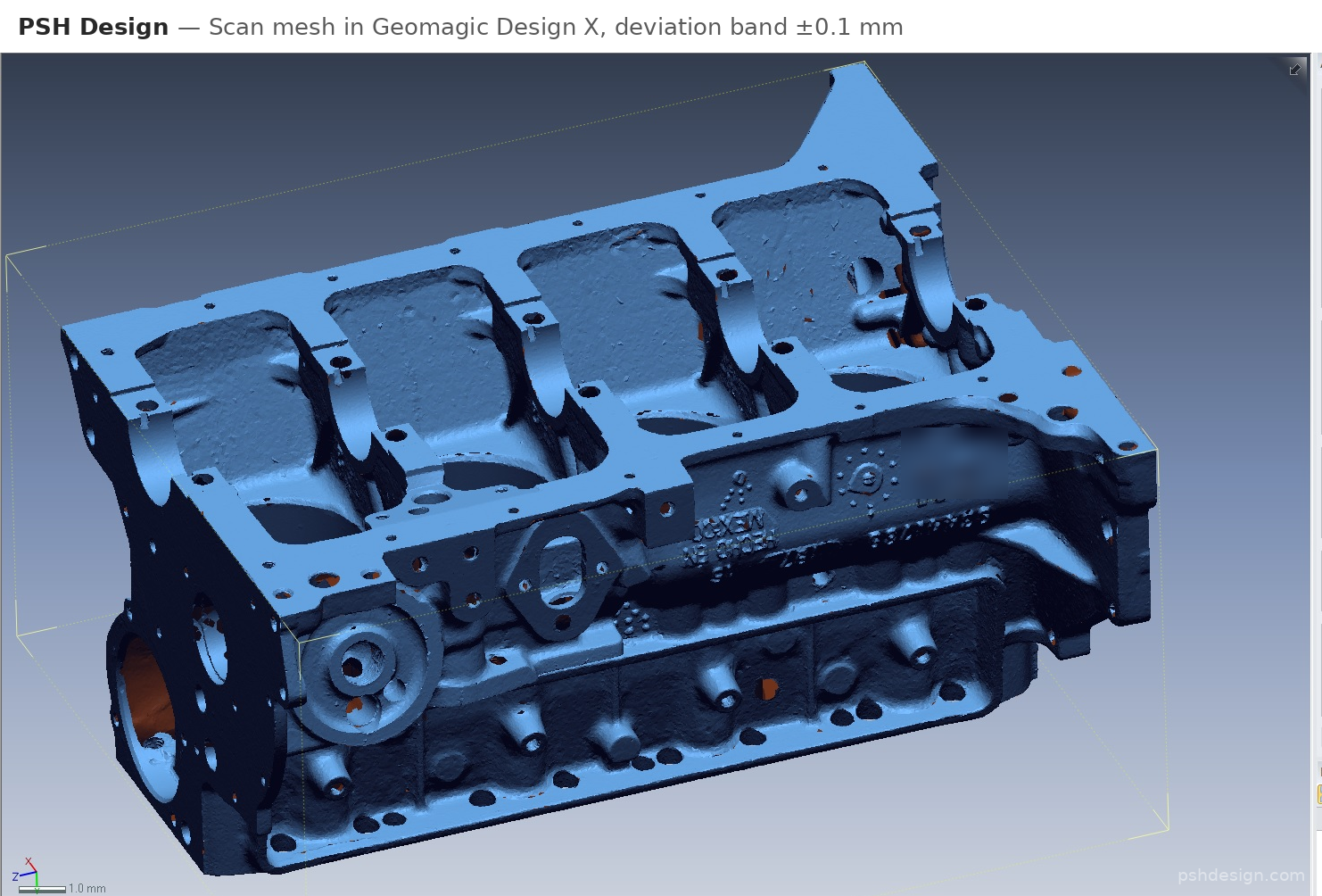
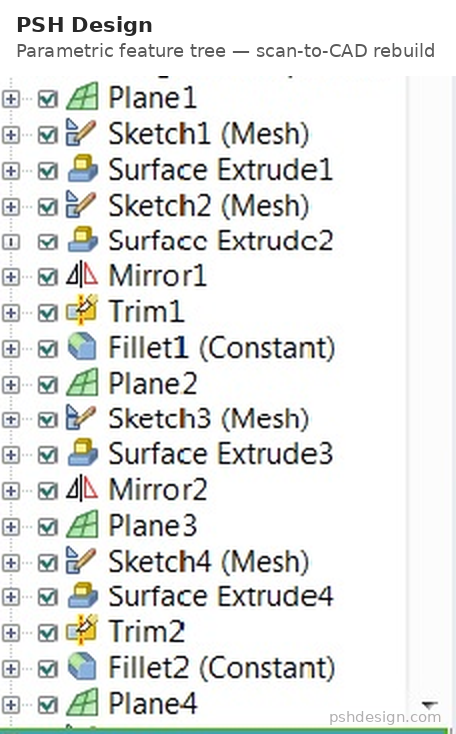
That is a feature tree from one of our rebuilds: Sketch (Mesh) → Surface Extrude → Mirror → Trim → Fillet (Constant), four times over. Each fillet is a fillet feature with a value someone can change. The mirrors are there because the part is symmetric and somebody decided it should stay symmetric. No automatic command produces that tree, because none of those decisions is in the mesh.
An experienced designer can work across several packages and produce a negative file as though it had been drawn from scratch. An inexperienced one leaning on the automatic commands is far more likely to bury problems in it.
The difference is not the software. It is whether the person holding it has a mechanical engineering foundation — seeing how the part was made, where it drew from the mold, which faces are mating faces, which dimensions are nominal and which are only process variation.
Native or Neutral
A correctly rebuilt model can still be useless at the last step, because it arrived in the wrong format.
STEP and Parasolid are neutral formats. They open everywhere, and that is their advantage. What survives the trip is geometry. What does not survive is build history — the feature tree, the constraints, the meaning of each face.
One exception worth stating correctly, because it is often misread: STEP AP242 is the current reference for carrying PMI and GD&T — tolerances, annotations, product notes. That is annotation data, not an editable feature tree; the parametric portion of the specification is essentially unimplemented by CAD vendors. AP242 addresses communicating intent. It does not address editing the model.
Native format — the file of the CAD system the recipient actually runs — carries the history with it.
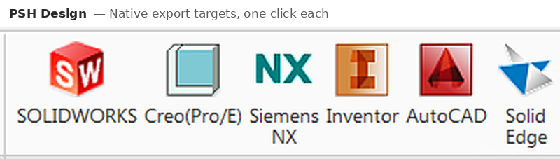
Why this matters more to an inspection lab than to anyone else: the end customer runs one CAD system, not seven. Hand them STEP and they can measure it and machine from it, but any change starts from geometry rather than from intent. Hand them the correct native file with its feature tree and they open it and work the same day.
The difference between those two outcomes is the difference between “this lab can deliver CAD” and “this lab delivers CAD that works”. The second order depends on the second version.
There is one more layer: the 2D documentation that travels with the model. Drawings to ASME Y14.5 and to ISO 1101 do not merely differ in symbols — they rest on two opposed principles:
- ISO 8015 — the Independency Principle. Size tolerance and geometric tolerance are satisfied independently of each other, unless the drawing states a relationship.
- ASME Y14.5 — Rule #1, the envelope requirement. Size tolerance simultaneously controls form.
The same drawing, read under the two standards, can produce two different inspection results. Not a difference in drafting convention — a difference in whether the part passes.
Current editions: ASME Y14.5-2018 (R2024) and ISO 1101:2017, adopted in Germany as DIN EN ISO 1101:2017-09.
Which convention applies is set by the drawing and the contract, not by geography — but geography is a good predictor of what the drawing will say, and of what the shop will assume if the drawing is silent. So the rule of thumb is: ask which convention governs, and follow the one the part will be inspected to rather than the one the model was built in.
Where PSH Design Fits
Everything above holds whether or not a lab ever works with us. This section is short, because the detail lives on the reverse engineering service page.
PSH Design is a design studio in Hanoi, working since 2009. We rebuild scan data, CMM data and drawings as parametric CAD for manufacturers in Germany, Japan, the United Kingdom and the United States — roughly 300 parts and 3,000 hours a year since 2009, without a failed part. Parts have run from a few millimeters to 80 meters.
On “without a failed part”. The term needs defining or it is only a slogan. It means no part we delivered has been returned to be rebuilt, and none has caused an error downstream in a mold, a fixture or a machining operation. Models do get changed after delivery — a dimension queried, a radius revised after a design change, a format re-exported for a different seat — and that is ordinary work on a live model, not what we are counting.
We work under the lab’s name. The scanning stays with you. The client relationship stays with you. We do not appear in the package that reaches your end customer, we do not contact them, and we do not take work from them afterwards. Our customer is the lab, not the lab’s customer.
We deliver native to SolidWorks, Creo, CATIA, NX, Inventor, Solid Edge and AutoCAD, with STEP and Parasolid alongside, and 2D documentation to DIN, ASME Y14.5 or JIS convention.
Normal lead time is two days for a mechanical part, and we treat that as a specification rather than an estimate — the data for one part is rarely waiting for one person. We work in English and Japanese, and we are on Hanoi time, UTC+7: that gives a US lab an overnight gap and a European lab an overlap across most of its morning. What that shorter wait is worth to the plant on the other end is worked through here. Hours by part type, and what makes a job run longer, are in Reverse Engineering Cost and Lead Time.
Since 2009, roughly 300 parts a year, without a failed part. By that we mean none has come back unusable and none has had to be rebuilt from scratch at the customer’s expense. Every model carries a lifetime warranty — find an error five years on and we fix it at no charge.
On confidentiality. Your customer’s data stays your customer’s data. Every job runs under NDA by default — not on request, and not as an extra step you have to ask for. We do not reuse customer geometry in our own material without permission.
Input and output lists in full, hours by part type, and terms of engagement are on the service page.
What We Do Not Take On
We do not take: pure modeling work that does not need a mechanical engineering foundation — not out of snobbery, but because it is not where we add value and there are cheaper places to have it done · automated scan-to-3D-print conversion for consumer products, toys and decorative items · freelance-style engagements, taken one job at a time with no long-term commitment.
We only take: long-term B2B partnerships · a lifetime warranty on every model — find an error five years on and we fix it at no charge · NET 30, properly invoiced.
Send One Part
The only way to find out whether a supplier can do the work is to watch them do it.
Send us one part — a scan, a CMM report, or a drawing. Raw is fine: holes, noise, fixture geometry still attached. Tell us which CAD system the end customer runs and what the part is for, and if a drawing exists, send that too even if it is old and faint.
We come back with a question or two, then with the model — native to the system you named, plus STEP, plus a deviation report like the ones above. We build it at our cost. It opens in your CAD system, measures, edits, and goes in front of the shop you trust. Judge it against your own standards, before any commercial conversation.
If it does not measure up, the only thing lost is the time it took to send the file.
For the commercial side — what this capability costs to build in-house, what a day of lead time is worth to the plant waiting on it, and how a measurement business actually grows — see What CAD In-House Costs, What a Day Costs, and What Actually Grows a Lab.
PSH Design
17+ years of CAS, Class A Surfacing, CAD and Reverse Engineering for Automotive, Aerospace, Medical and Industrial, to OEM standard.
Concept Design & CAS · Class A Surfacing · CAD Engineering · Reverse Engineering
Work of this kind is easier to judge than to describe.